background image

4 Maintenance


Endura AZ20 oxygen monitor | Pumped reference air unit |

INF09/027 Rev. D

7

4 Maintenance

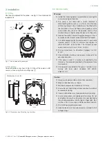
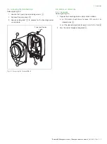
4.1 Replacing the air filter

1. Remove the pump cover – see section 3.4, page 5.

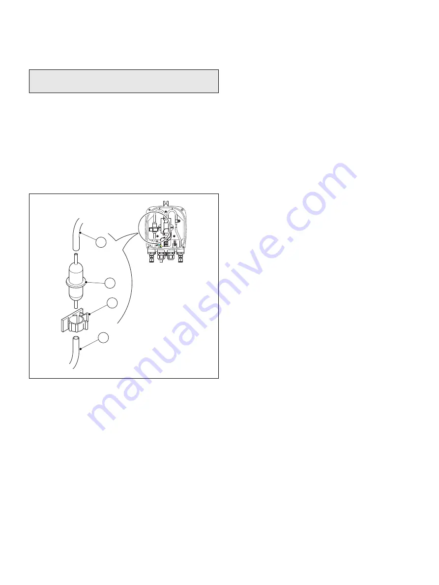
Referring to Fig. 4.1:

2. Disconnect the top tube 

A

 from air filter 

B

.

3. Disconnect the lower tube 

C

 from air filter 

B

.

4. Release clip 

D

 and carefully remove air filter 

B

 by pulling it

out of the clip. 

5. Discard air filter 

B

6. Fit a new filter by reversing steps 1 to 4.

Note.

Isolate the pump from power and air supplies before

replacing the air filter.

Fig. 4.1 Replacing the Air Filter 

A

C

B

D

Summary of Contents for AZ200 770

Page 1: ...uipment is not impaired do not use or install this equipment in any manner other than that which is specified in this manual 2 2 Health Safety Note The pump cannot be used with multiple probes simultaneously Description ABB Part Number 1 4 BSP Metric 230 V AC 50 60 Hz AZ200 770 1 4 BSP Metric 115 V AC 50 60 Hz AZ200 771 1 4 NPT Imperial 230 V AC 50 60 Hz AZ200 772 1 4 NPT Imperial 115 V AC 50 60 H...

Page 2: ...he enclosure or remove the barrier This symbol indicates that the marked item can be hot and should not be touched without care This symbol indicates the presence of devices sensitive to electrostatic discharge and indicates that care must be taken to prevent damage to them The European Union RoHS Directive and subsequent regulations introduced in member states and other countries limits the use o...

Page 3: ...oblems with installation starting or using the pump please contact the company that sold it to you If this is not possible or if the results of this approach are not satisfactory please contact the manufacturer s Customer Service 2 9 Potential safety hazards The following potential safety hazards are associated with operating the system Electrical line voltage Warning The installation of the pump ...

Page 4: ... with relevant national and local standards Use cable appropriate for the load currents 3 core cable rated 5A and 90 C 194 F minimum that conform to either IEC 60227 or IEC 60245 The terminals accept cables from 0 8 to 2 5 mm2 18 to 14 AWG The pump conforms to Installation Category II of IEC 61010 After installation there must be no access to live parts for example terminals If the pump is used in...

Page 5: ...osen cable gland C to prepare for the incoming power supply cable 3 5 Electrical connections 3 5 1 Preparation Referring to Fig 3 4 1 Prepare the incoming power supply cable as follows a cut the outer sheath back to leave 100 mm 4 0 in sleeved wires A b cut the sleeved wires back to leave 5 mm 0 2 in tails B 2 Pass the cable through cable gland C Fig 3 3 Accessing the Terminal Block B C A Pump Ide...

Page 6: ...ction 6 Refit the pump cover by reversing the procedure in Section 3 4 3 6 Reference air connections Referring to Fig 3 5 1 It is important that air to the pump inlet is clean and dry If necessary connect a pipe to the pump suction inlet A and ensure the other end of the pipe is located in a clean dry area 2 Connect the pumped reference air outlet B directly to the reference air inlet on the probe...

Page 7: ...ring to Fig 4 1 2 Disconnect the top tube A from air filter B 3 Disconnect the lower tube C from air filter B 4 Release clip D and carefully remove air filter B by pulling it out of the clip 5 Discard air filter B 6 Fit a new filter by reversing steps 1 to 4 Note Isolate the pump from power and air supplies before replacing the air filter Fig 4 1 Replacing the Air Filter A C B D ...

Page 8: ...or modify the contents of this document without prior notice With regard to purchase orders the agreed particulars shall prevail ABB does not accept any responsibility whatsoever for potential errors or possible lack of information in this document We reserve all rights in this document and in the subject matter and illustrations contained therein Any reproduction disclosure to third parties or ut...

Reviews: