background image

6

 SI/ANAINST/001-EN

| Aztec 600 | Piston assembly | Single- and multi-stream colorimetric analyzers

4.3 Removing a piston

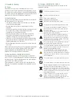
Referring to Fig. 4.2: 
1.

Turn handle 

A


1

/

4

 turn clockwise, pull the analytical 

section forward and allow it to rest against its stops. 

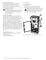
Referring to Fig. 4.3:
2.

Disconnect the measurement cell ribbon cable 

B

 from 

the connector on the back of the measurement cell.

3.

Remove 4xM4 screws 

C

 and remove the measurement 

cell assembly. 

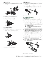
Referring to Fig. 4.4:
4.

Depress catch 

D

 and remove cover 

E

.

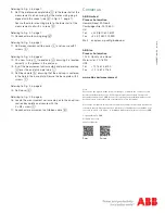
Referring to Fig. 4.5,
5.

Invert the measurement cell assembly, remove 4 screws 

F

 and remove base plate 

G

.

6.

Remove sample tube end face sealing cap 

H

 and remove 

seal 

I

. Discard the seal.

7.

Remove all traces of fluid from the inside of sample tube 

J

.

IMPORTANT (NOTE)

Perform this procedure if the piston is seized. 

DANGER – Serious damage to health / risk to life

Isolate the analyzer from mains power supplies before 
performing this procedure.

WARNING – Bodily injury

— do not allow any fluid from the measurement cell 

sample tube to come into contact with either the 
skin or any metallic / electronic parts of the 
analyzer. The fluid is contaminated with acid from 
the reagents used in the analyzer – wipe up any 
spillages immediately

– wear appropriate PPE when emptying any liquid 

from the piston

Fig. 4.2 Opening the analytical section

Fig. 4.3 Removing the measurement cell assembly

Fig. 4.4 Removing the measurement cell cover

Fig. 4.5 Removing the measurement cell base plate 

Summary of Contents for Aztec 600

Page 1: ...nual clean refer to Section 4 2 page 5 before removing it for return refer to Section 4 3 page 6 if the piston is seized a manual clean may not be possible remove it from the housing refer to Section...

Page 2: ...rotection provided by the equipment may be impaired 3 4 Symbols CEI IEC 61010 1 2001 2 One or more of the following symbols may appear on the equipment labelling Protective earth ground terminal Funct...

Page 3: ...ose involved in the life cycle of electrical and electronic equipment In conformity with European local and national regulations EU Directive 2002 96 EC stated above electrical equipment marked with t...

Page 4: ...the correct working of the instrument and the electrical integrity or the CE compliance of the instrument If you have any problems with installation starting or using the instrument please contact the...

Page 5: ...When the clean is complete the and keys to navigate to the Operation field and select Reset Pump 7 The piston can now be removed from the instrument and returned to the factory for repair refer to Se...

Page 6: ...e sealing cap H and remove seal I Discard the seal 7 Remove all traces of fluid from the inside of sample tube J IMPORTANT NOTE Perform this procedure if the piston is seized DANGER Serious damage to...

Page 7: ...ston base complete with seal and O ring into the new piston top W and secure loosely with new piston cone adjusting screw X and spring washer Y 4 Insert new piston assembly Q into the top of new sampl...

Page 8: ...4 3 page 6 16 Locate the measurement cell assembly onto the analytical section back plate and secure with the 4 x M4 screws C 17 Reconnect measurement cell ribbon cable B Note We reserve the right to...

Reviews: