Contact us
SI/ANAINST/001-E
N
05.2016
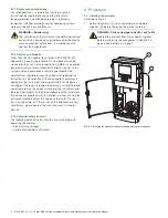
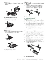
Referring to Fig. 4.8, page 7:
9.
Refit the motor and sample tube
O
to the lower half of the
measurement cell, ensuring that the motor wiring plug is
aligned with the socket (see
M
in Fig. 4.7, page 7).
Secure the motor mounting plate to the lower half of the
measurement cell with 4 screws
N
.
Referring to Fig. 4.7, page 7:
10. Reconnect motor wiring plug
M
.
Referring to Fig. 4.6, page 7:
11. Refit measurement cell top cover
L
and secure with 2
screws
K
.
Referring to Fig. 4.5, page 6:
12. Fit a new O-ring
I
to end cap
H
, ensuring it is located
correctly in the groove in the end cap.
13. Invert the measurement cell assembly and position end cap
H
over the end of sample tube
J
.
14. Refit base plate
G
ensuring that the end cap is centered
in the hole in the base plate. Secure the base plate with 4
screws
F
.
Referring to Fig. 4.4, page 6:
15. Refit cover
E
.
Referring to Fig. 4.3, page 6:
16. Locate the measurement cell assembly onto the analytical
section back plate and secure with the
4 x M4 screws
C
.
17. Reconnect measurement cell ribbon cable
B
.
Note
We reserve the right to make technical changes or modify the contents of this
document without prior notice. With regard to purchase orders, the agreed
particulars shall prevail. ABB does not accept any responsibility whatsoever for
potential errors or possible lack of information in this document.
We reserve all rights in this document and in the subject matter and illustrations
contained therein. Any reproduction, disclosure to third parties or utilization of its
contents in whole or in parts – is forbidden without prior written consent of ABB.
Copyright© 2016 ABB
All rights reserved
3KXA833145R4301
ABB Limited
Process Automation
Howard Road, St. Neots
Cambridgeshire, PE19 8EU
UK
Tel:
+44 (0)870 600 6122
Fax:
+44 (0)1480 213 339
Mail:
enquiries.mp.uk@gb.abb.com
ABB Inc.
Process Automation
125 E. County Line Road
Warminster, PA 18974
USA
Tel:
+1 215 674 6000
Fax:
+1 215 674 7183
www.abb.com/measurement
Sales
Service


