B2342
Emax VF
12/66
Doc. no.
Model
Apparatus
Scale
Page No
1SDH000909R0001
5.3.2. Withdrawable circuit-breaker
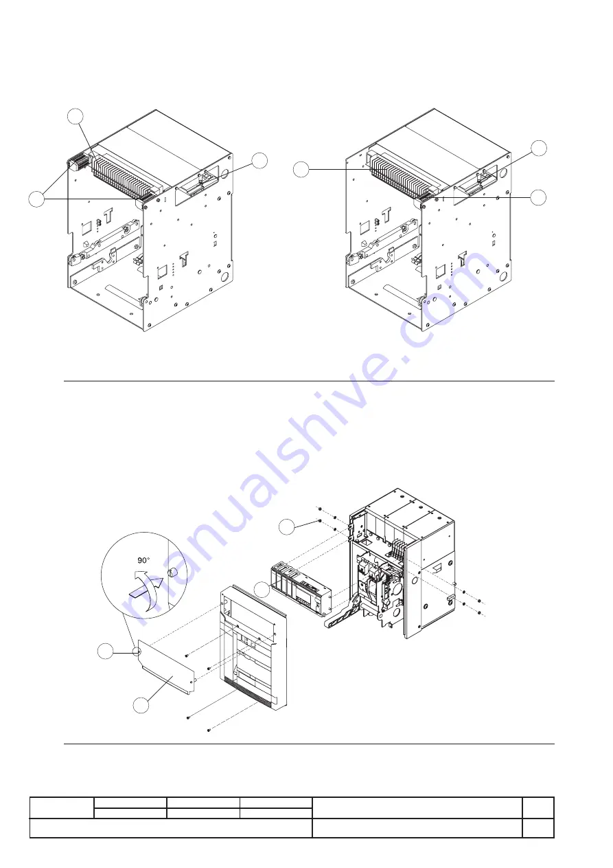
For connection of the moving part to the auxiliary circuits, a connection with sliding contacts is available on the fixed part (see figure),
identified by code X on the electrical circuit diagram.
The terminals of the fixed connector are immediately accessible when the compartment door is open.
Furthermore a terminal box identified by code XF is available for connecting the position contacts of the moving part in relation to
the fixed part.
The connector and terminal box have screw terminals.
Fig. 20
1
2
3
E2 - E3
5 contacts in position
1
2
3
E2 - E3
10 contacts in position
Caption
1 Sliding contacts (X)
2 Terminal box for position contacts (XF)
3 Position contacts
5.4. Conversion of the auxiliary contacts or of the signalling contacts (disconnected - test isolated - connected), from normally
closed (opening) to normally open (closing) or vice versa
The contacts are wired at the factory as shown on the electrical circuit diagram. If it is necessary to change their state for installation
requirements, proceed as follows.
a) Auxiliary contacts
To access the auxiliary contacts, carry out the following operations:
-
remove the front protection (3) of the release by taking action on the blocks (1) as shown in the figure
-
remove the protection release (4) removing the side nuts (2) and then sliding the release out from the front of the circuit-breaker.
Fig. 21
SAC
E PR
122/V
F
1
3
4
2
Being of the two-way type (changeover contacts), the auxiliary contacts can be modified from break contacts to make contacts and
vice versa simply by moving the output conductor from one position to the other, as shown in the figure.


