B2342
Emax VF
45/66
Doc. No
Model
Apparatus
Scale
Page No
1SDH000909R0001
12.3.6.5. SIGNALLING Module
In this menu it is possible to check the Input Status and to perform the autotest of the frontal LED, and related contact.
12.3.7. About this section
In this section it is possible to view the main CB and trip unit information.
12.4. Modules
12.4.1. PR120/D-M
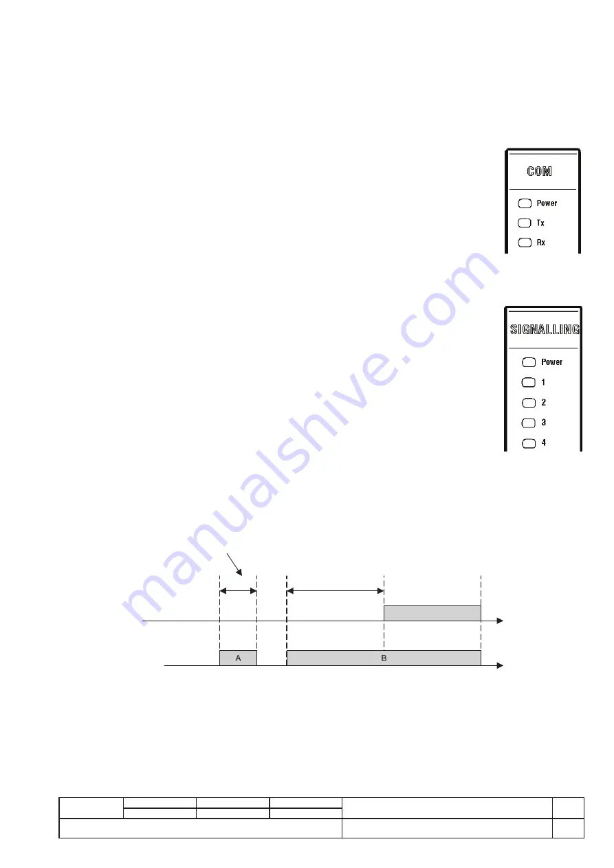
The optional module PR120/D-M is the dedicated communication module for connecting the trip unit to a Modbus network, and for
remote supervisory and control activities on the circuit-breakers.
The front of the trip unit features 3 LEDs:
- Power: if the AUX is present and the unit is correctly turned ON.
- Tx: During communication this LED will blink. Data direction: from trip unit to external. Without communica-
tion on bus, the LED is turned ON.
- Rx: during communication this LED will blink. Data direction: from external to trip unit. Without communi-
cation on bus, the LED is turned OFF.
12.4.2. PR120/K
The optional module PR120/K is the dedicated contact module to extend the performing of trip unit input/
output. The module enables the local signaling of alarms and CB trips.
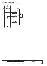
There are two possible configurations for the SIGNALLING module:
- default configuration: 1 digital input programmable, 3 contacts with pole in common, 1 independent contact;
- alternative configuration: 4 independent contacts. In this case, the digital input is wired, but not brought up to the terminal block.
The two configurations are alternative to each other. You can switch from one configuration to the other without changing the module,
by using a different wiring, as illustrated in the wiring diagrams.
The frontal of the trip unit features 5 LEDs:
- Power: if the AUX is present and the unit is correctly turned ON.
- 1: report the status of contact 1: LED tuned ON means Contact 1 closed.
- 2: same function of 1, related to contact 2.
- 3: same function of 1, related to contact 3.
- 4: same function of 1, related to contact 4.
No LED is used to show the status for Digital input.
12.4.2.1. Digital Input
The unit enables the digital input to be associated with the following functions:
- outside trip control;
- zeroing release trips;
- resetting PR120/K contacts;
- local/remote enabling;
- for the load control function, the module can be used as an actuator.
To enable the Input, provide a signal 24Vdc ±20%.
There is an input with a configurable function in the Signalling module. The figure shows two cases, A and B, in which the input status
is active; in case A the input does not stay valid beyond the enabling delay so the associated action does not take place, whereas in
case B the action takes place after the preset delay.
Times shorter than the delay
Preset delay
Consequent action
Action
Input status
You can select the action associated with the input, i.e. the action that takes place after the programmed delay, when the input is enabled.
You can select one of the following actions:
- Generic: no specific action is associated with the input. The status of the input is shown on the available display and remotely via
the bus.
- Trip test: when the input is enabled for the specified delay, a trip test is performed.
- Trip reset: when the input is enabled for the specified delay a trip reset is performed.
- Dial Local: when the input is enabled for the specified delay, there is a forcing of the dialogue local mode.
- Signalling module reset: when the input is enabled for the specified delay, the status of the relays in the PR120/K module is reset.
- Energy reset: when the input is active for the specified delay, the energy meters are reset.
Through the “Delay” parameter, you can specify the time to elapse before the input is enabled within the range 0s...100s (step 0.01s).


