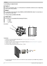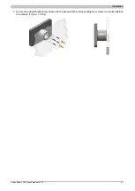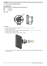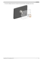
Installation
34
Power Panel FT50 User's manual V1.19
5.4 Installing accessories
5.4.1 General information
Gaskets
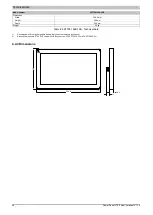
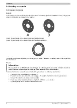
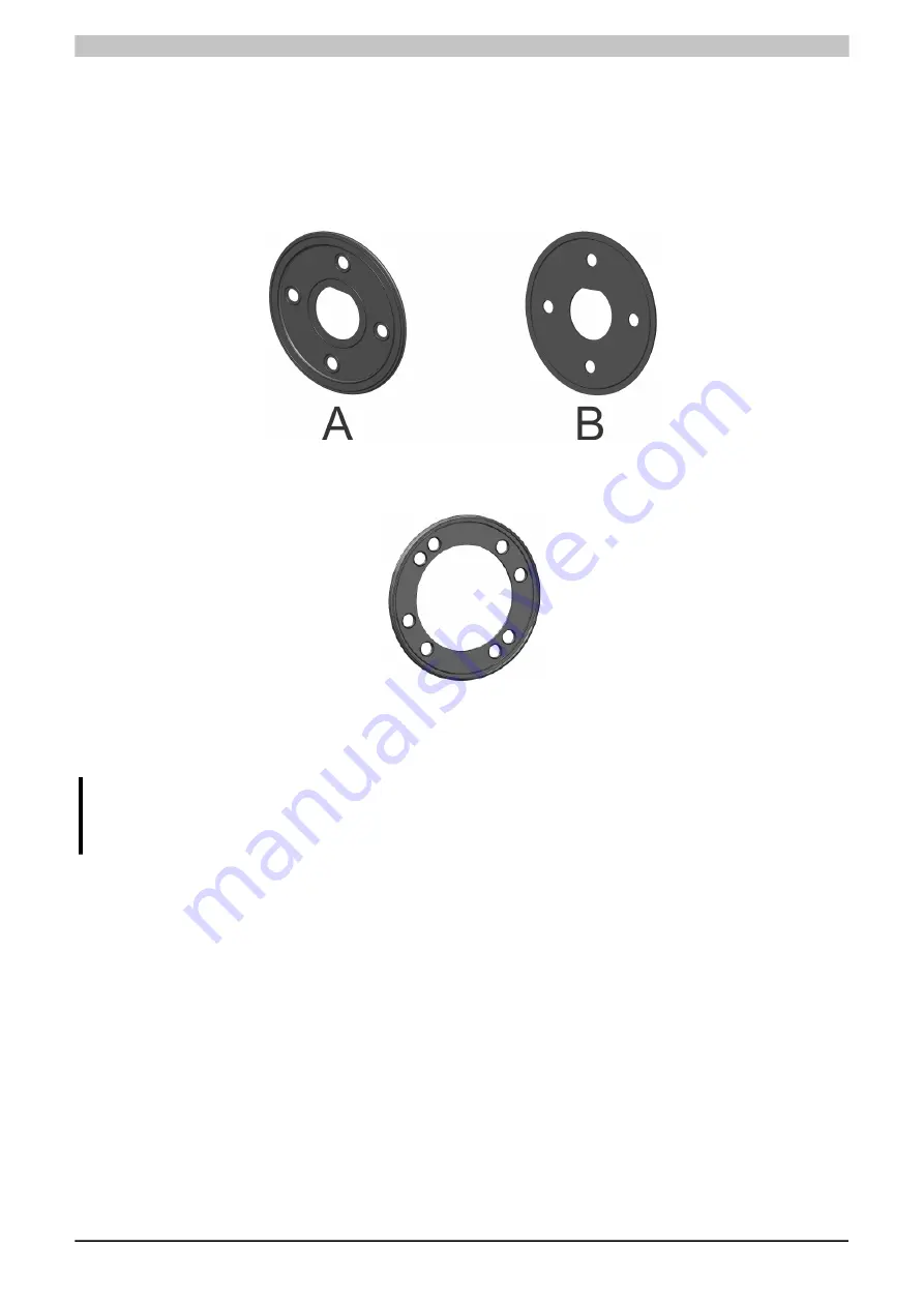
In the following installation instructions, it is important to ensure that the gaskets are installed correctly. The graphics
shown in this section are intended to illustrate this.
View A: Shows the side of the gasket that should face the bracket.
View B: Shows the side of the gasket that should face the panel/device.
This gasket must be placed between the bracket and a surface. The side of the gasket shown in the image must
face the bracket.
Screws
Information:
The supplied screws of the brackets and flanges are not designed to secure the terminals to walls or
control cabinets. These only serve to secure the accessories to the terminal itself.
To secure the terminals to a wall or control cabinet, they must meet the following specifications:
•
The terminal must be installed on a flat surface.
•
The wall or control cabinet must be able to support the weight of the terminal including accessories.
•
Screws: M5 screw thread, standard stainless steel
•
The screws on the bracket must reach a depth of 4 to 5.5 mm on the bracket.
•
Tightening torque for the screws on the bracket: 1.3 Nm

