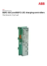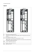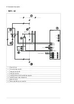
Layout
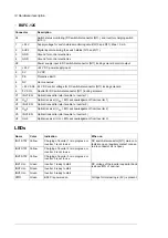
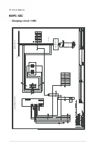
BSFC-12C
3:5
5$7,1*6
6833/<92/7$*(;
9
'&
P$
62/(12,'&21752/
287387;
9'&
0$;$
(;&,7$7,2192/7$*(
287387;
9'&0$;P$
23(57(03(5$785(
0$;
&
%6)&
&
6:,
7
&+
)86(
&21752//(5
8'&
8'&
72%(86(':,7+
$%%'5,9(621/<
0$;,0805$7('
6<67(092/7$*(
8/9$&
,(&9$&
8'&
;
9
9
3(
9
62/
9
62/
;
9
$8;
*1'
*1'
67$7
6
9
9
6
9
9
6
',6
(1
',6
(1
',6
(1
,19
,19
,19
67$7
67$7
9
9
67$7
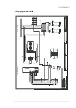
BSFC-02C
3:5
5$7,1*6
6833/<92/7$*(;
9+]P$
9+]P$
62/(12,'&21752/
287387;9
$&0$;$
(;&,7$7,2192/7$*(
287387;
9'&0$;P$
23(57(03(5$785(
0$;
70
&
%6)&&
6:,
7
&+
)86(
&21752//(5
,1'&217(4
3'
8'&
8'&
72%(86(':,7+
$%%'5,9(621/<
0$;,0805$7('
6<67(092/7$*(
8/9$&
,(&9$&
8'&
;
/
1
3(
/62/
162/
;
9
$8;
*1'
*1'
67$7
6
9
9
6
9
9
6
',6
(1
',6
(1
',6
(1
,19
,19
,19
67$7
67$7
9
9
67$7
Switch status monitoring (Q10 and Q11).
X4
Power supply input for BSFC and operating voltage output for DC switch-disconnector locking
solenoid.
X5
Fiber optic links to inverters 1, 2 and 3.
V1…V6
Enable switches for charging circuit monitoring (inverters 1, 2 and 3).
Note:
The BSFC unit does not allow the closing of the DC switch-disconnector unless monitoring
is enabled for at least one inverter module.
S1…S3
Inverter charging status LEDs (3 pcs).
STAT
1…3
Inverter “ready for start” LEDs (3 pcs).
U
DC
1…3
BSFC power on LED.
PWR
12 Hardware description
Summary of Contents for BSFC-02C
Page 1: ... ABB INDUSTRIAL DRIVES BSFC 02C and BSFC 12C charging controllers Hardware manual ...
Page 2: ......
Page 4: ......
Page 10: ...10 ...
Page 30: ...30 ...

