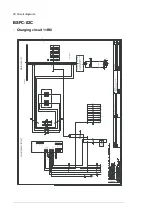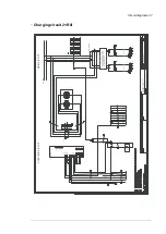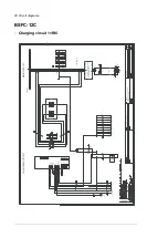
Inverter power switch-off sequence
WARNING!
Do not open the DC switch-disconnector [Q11] while the inverters are loaded.
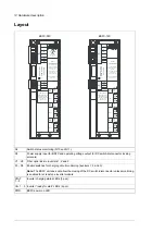
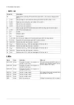
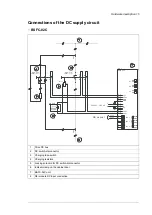
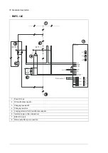
The terms and designations used in the table below refer to the diagrams in section
Connections of the DC supply circuit
.
1.
User stops the inverters.
2.
User turns DC switch-disconnector [Q11] handle to position 0 (OFF).
•
DC switch-disconnector [Q11] disconnects inverter(s) from the DC power supply.
•
Contact 13-14 of DC switch-disconnector [Q11] switches off the AUX2 signal to the
BSFC unit. BSFC switches INV1 EN signal off, which disables inverter start.
•
Auxiliary contact 21-22 closes, energizing the solenoid of DC switch-disconnector
[Q11]. The solenoid releases the locking mechanism of the DC switch-disconnector.
Operation of the handle is possible as long as inverter DC voltage remains high.
•
INV UDC
and
PWR
LEDs are on. The
Charging OK
light [P11] on the cabinet door
is on.
•
The inverter DC voltage decreases to zero gradually. When below 80% of nominal:
•
Inverters switch off UDC signals from BSFC unit.
•
BSFC switches off the operating voltage to solenoid of DC switch-disconnector
[Q11]. Locking mechanism activates, which prevents turning the handle into
position 1 (ON).
•
INV UDC
and
PWR
LEDs are on.
Locking solenoid control
The DC switch-disconnector [Q11] has a locking solenoid, which prevents the operation of
the handle when the solenoid is de-energized. You can only close the DC switch-disconnector
[Q11] when:
•
DC voltage of all inverter modules monitored by the BSFC unit exceed 80% of the
nominal value. (BSFC receives
U
DC
signals from inverters and energizes the solenoid).
•
DC switch-disconnector [Q11] handle is in position 0 (OFF).
18 Hardware description
Summary of Contents for BSFC-02C
Page 1: ... ABB INDUSTRIAL DRIVES BSFC 02C and BSFC 12C charging controllers Hardware manual ...
Page 2: ......
Page 4: ......
Page 10: ...10 ...
Page 30: ...30 ...


