8
C1 3 0 0/A DVA NCE D CI RCU L A R CH A RT R ECOR DE R
| C I/C 1 3 0 0 - EN R E V. C
…5 Electrical connections
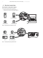
Selecting the analog input type(s)
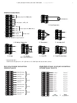
Plug-in links are used to select the input type:
• Channel 1 PL1 & PL8 on the main PCB (Figure 6)
• Channels 2 to 4 PL1 & PL3 on the module (Figure 7).
Figure 6 Selecting the input type (main board)
Figure 7 Selecting the input type (I/O modules)
mA V RTD & Resistance
5
4
8
1
2
3
1
4
2
3
1
4
PL8
PL8
PL1
PL1
5
4
8
1
mV THC
2-wire Transmitter
All other input types
All other input types
2-wire Transmitter
mA V RTD & Resistance
PL1
PL1
PL3
PL3
5
8
4
1
5
8
4
4
1
1
3
2
4
1
3
2
mV THC

