97
APPENDIX A – CONTROL TEMPLATES…
The
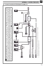
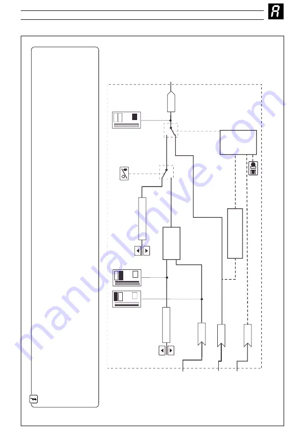
Analog Backup
provides a backup for a master controller. In normal operation (remote control mode selected) the COMMANDER 500’s
current output follows the master controller’s output value. A fault in the master system can be identified either by detecting
a low signal on the master
output (template 5) or via a digital signal (template 6). When a fault is detected the COMMANDER 500 switches into local contro
l mode and the process
is controlled by the PID output of the COMMANDER 500. The COMMANDER 500 PID algorithm continually tracks the master output valu
e to ensure
bumpless transfer from remote to local mode operation. When the master signal is restored or the digital input returns to its n
ormal state the
COMMANDER 500 switches back to remote control mode (i.e. COMMANDER 500 output = master output).
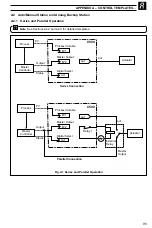
The analog backup station can be used in series or in parallel with the master output signal. (See Fig. A1). Parallel operation
is achieved by using
relay 1 in the COMMANDER 500 to energize an external relay (with suitable changeover contacts for switching low level signals)
which selects the
output to be routed to the actuator.
LSPt
I/P2
I/P1
di.1
PV
Process V
ariable
PID
Controller
Low Signal Select
(Alarm A1)
Local/
Remote
Select
•1
•2
•1
T
emplate 5 only
.
Alarm
A1 trip value can be set to give the desired low signal detection
•2
T
e
mplate 6 only
.
Master Output
Digital Select
Manual Output
L
LR
ao1
OP1
Local Set Point
A2.3
Analog Backup (Templates 5 and 6)


