background image


Safety


Product manual 2CKA001373B8563 

│6


2.2 

Intended use 


This device is a room temperature controller for decentralized flush-mounted installation. For 
controlling fan coil units or blower convectors. 

The device is intended for the following: 


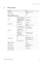
Operation according to the listed technical data 


Installation in dry interior rooms and suitable flush-mounted boxes 


Use with the connecting options available on the device 

The intended use also includes adherence to all specifications in this manual. 


2.3 

Improper use 


Each use not listed in Chapter 2.2 “Intended use“ on page 6 is deemed improper use and can 
lead to personal injury and damage to property. 

ABB is not liable for damages caused by use deemed contrary to the intended use of the 
device. The associated risk is borne exclusively by the user/operator. 

The device is not intended for the following: 


Unauthorized structural changes 


Repairs 


Outdoor use 


The use in bathroom areas 


Insert with an additional bus coupler 


2.4 

Target group / Qualifications of personnel 


Installation, commissioning and maintenance of the device must only be carried out by trained 
and properly qualified electrical installers. 

The electrical installer must have read and understood the manual and follow the instructions 
provided. 

The electrical installer must adhere to the valid national regulations in his/her country governing 
the installation, functional test, repair and maintenance of electrical products. 

The electrical installer must be familiar with and correctly apply the "five safety rules" (DIN VDE 
0105, EN 50110): 

1.  Disconnect 
2.  Secure against being re-connected 
3.  Ensure there is no voltage 
4.  Connect to earth and short-circuit 
5.  Cover or barricade adjacent live parts 


Summary of Contents for Caldion FCR-F-2-4.2.21.1 Series

Page 1: ...Product manual 16 12 2021 ABB free home FCR F 2 4 2 21 1 xx Caldion RoomTemperature controller FCR F 2 4 6 21 1 xx Caldion RoomTemperature controller Branding Release 2018 01 01 ...

Page 2: ...tion 16 5 1 Planning instructions 16 5 2 Safety instructions 16 5 3 Installation site 17 5 4 Mounting 18 5 5 Electrical connection 20 6 Commissioning 25 6 1 Allocation of devices and definition of channels 25 6 1 1 Add device 26 6 2 Setting options per channel 29 6 2 1 Parameter settings of room temperature controller 30 6 2 2 Open overview of devices 33 6 2 2 1 Parameter settings of fan coil actu...

Page 3: ...Table of contents Product manual 2CKA001373B8563 3 10 Notes 48 11 Index 49 ...

Page 4: ... property and ensure both reliable operation and a long service life for the device Please keep this manual in a safe place If you pass the device on also pass on this manual along with it ABB accepts no liability for any failure to observe the instructions in this manual If you require additional information or have questions about the device please contact ABB or visit our Internet site at https...

Page 5: ... symbol in connection with the signal word Danger indicates an imminently threatening danger which leads to death or serious irreversible injuries Warning Serious damage to health The respective warning symbol in connection with the signal word Warning indicates a threatening danger which can lead to death or serious irreversible injuries Caution Damage to health The respective warning symbol in c...

Page 6: ...ociated risk is borne exclusively by the user operator The device is not intended for the following Unauthorized structural changes Repairs Outdoor use The use in bathroom areas Insert with an additional bus coupler 2 4 Target group Qualifications of personnel Installation commissioning and maintenance of the device must only be carried out by trained and properly qualified electrical installers T...

Page 7: ...rformed by authorised and qualified electricians Disconnect the mains power supply before installation or dismantling Never use the device with damaged connecting cables Do not open covers firmly bolted to the housing of the device Use the device only in a technically faultless state Do not make changes to or perform repairs on the device on its components or its accessories Caution Risk of damagi...

Page 8: ...ing depot All packaging materials and devices bear the markings and test seals for proper disposal Always dispose of the packaging material and electric devices and their components via the authorized collecting depots and disposal companies The products meet the legal requirements in particular the laws governing electronic and electrical devices and the REACH ordinance EU Directive 2012 19 EU WE...

Page 9: ... element and also forms a sensor actuator unit within the free home system The integrated bus coupler makes the connection to the free home bus line possible The devices are pre programmed The devices must be parameterised for the use of the functions 3 1 Scope of supply The scope of supply only contains the flush mounted insert 1 the clip for the anti theft device 2 and the front cover 3 Two scre...

Page 10: ...e On Off FCR F 2 4 6 21 1 81 black 2 4 pipe On Off Table 1 Overview of types Caldion Room Temperature controller Article no Output channels Switching load Total load to terminal L Fx Vxx FCR F 2 4 2 21 1 xx 2 pipe 1 7 A FCR F 2 4 2 21 1 xx 2 pipe with additional heater 2 7 A FCR F 2 4 2 21 1 xx 4 pipe 2 7 A FCR F 2 4 6 21 1 xx 2 pipe 1 7 A FCR F 2 4 6 21 1 xx 2 pipe with additional heater 2 7 A FC...

Page 11: ...ted quickly Caldion room temperature controller control fans either as a single phase fan with up to three fan speeds via step or changeover actuation For speed controlled fans in changeover operation mode to ensure that no two fan speeds can be switched on simultaneously An additional programmable switch over delay is provided for this purpose Three phase drives are not supported The room tempera...

Page 12: ...s an overview of the possible functions and applications of the device Icon of the user interface Information Name Room temperature controller Type Sensor Made available by Room temperature controller Job type Regulates ABB free home fan coil actuators Table 2 Overview of functions ...

Page 13: ...g 2 Room temperature controller front view 1 Display with indication and control elements 1 2 Fig 3 Room temperature controller rear view 1 Top connection strip 2 Bottom connection strip 1 2 Fig 4 Room temperature controller bottom view 1 Temperature sensor 2 Programming button ...

Page 14: ...mm Nominal voltage 30 V DC SELV range 21 32 V DC Outputs Control output at F1 F2 F3 N VA VB N RO N 230 V AC 8 3 mA 5 2 A Resistive Inductive Total load current through terminal L Fx Vxx 7 A Total load of control output 0 10 VA COM 0 10 VB COM SELV range 0 10 V DC 1 5 mA 10 kohms Inputs E1 and E2 Physical inputs E1 and E2 10 V 1 mA E1 Standard window contact E2 NTC 10 01 10K B Constant 3936 3976 Ca...

Page 15: ...A001373B8563 15 4 1 Dimensional drawings Notice All dimensions are specified in mm All device types described in this manual have the same dimensions Fig 5 Dimensions of all described device types all dimensions in mm 86 86 52 16 34 2 ...

Page 16: ...t polarity Observe the relevant standards Danger Electric voltage Install the device only if you have the necessary electrical engineering knowledge and experience Incorrect installation endangers your life and that of the users of the electrical system Incorrect installation can cause serious damage to property e g due to fire The minimum necessary expert knowledge and requirements for the instal...

Page 17: ...allation sites The device should be mounted on a wall opposite the heat source The distance to side walls or door frames should be at least 50 cm The distance to the floor should be about 150 cm Do not mount the device on the wall Low outside temperatures have an effect on temperature regulation The room temperature controller must not come into direct contact with liquids Do not mount the device ...

Page 18: ...1 Insert the flush mounted insert into the flush mounted box Pay attention to the correct installation position Orientate yourself on the TOP marking 2 Screw the flush mounted insert in place Use the provided screws Fig 8 Fitting the front cover 3 Place the front cover on the lower edge of the flush mounted insert 4 Push the anti theft device clip about halfway into the provided shaft Pay attentio...

Page 19: ...nnection and installation Product manual 2CKA001373B8563 19 5 Press the front cover closed 6 Fig 9 Securing the device 6 Once the front cover is closed slide the clip all the way down to secure the device ...

Page 20: ...otice The physical input E1 is intended for the connection of a window contact If no window contact is connected the physical inputs E1 and COM must be connected with a cable closed contact On delivery the connections E1 and COM are connected with a cable Without a cable connection the device operates in frost heat protection mode Cconnection of two pipes with an electrical heater Notice When conn...

Page 21: ...Connection and installation Product manual 2CKA001373B8563 21 Connection FCR F 2 4 2 21 1 xx Fig 11 Connection two pipes 0 10 V Fig 12 Connection two pipes 0 10 V with electrical heater ...

Page 22: ...Connection and installation Product manual 2CKA001373B8563 22 Fig 13 Connection four pipes 0 10 V Connection FCR F 2 4 6 21 1 xx Fig 14 Connection two pipes On Off ...

Page 23: ...Connection and installation Product manual 2CKA001373B8563 23 Fig 15 Connection two pipes On Off with electric heater Fig 16 Connection four pipes On Off ...

Page 24: ...Connection and installation Product manual 2CKA001373B8563 24 Fig 17 Connection two pipes On Off with 3 point valve ...

Page 25: ... log themselves automatically into the System Access Point They transmit information about their type and supported functions See Functions on page 11 During initial commissioning all devices are given a universal name e g Sensor switch actuator 1 1gang The installer should assign names that are practical and specific for the system e g in Living room ceiling light The devices can be parameterised...

Page 26: ...ound plus icon 1 at the bottom right Menu Select component opens 3 Tap on the desired characteristic in the list of components The menu with the available devices functions and actuators opens 4 Select the desired device and pull it into the building plan via drag and drop Fig 19 Pulling the device out of the menu bar example illustration Notice for operation via a mobile phone The building plan f...

Page 27: ...vely for the selected application Fig 20 Pop up window with the suitable devices Identification The device can be identified via the serial number or via switching Identification via serial number Fig 21 Identification via serial number Compare the serial number and the short ID of the identification label which is glued on the device plan with the numbers and IDs in the list This is how the searc...

Page 28: ...o switch the device you can use the programming button on the bottom of the device Use a suitable tool with a diameter smaller than 2 mm Press the tool into the programming button to switch the device Specifying a name 1 Enter a name in text field 3 under which the application is to be displayed later e g Heating cellar 2 Tap the Save button to take over the adjustments This takes over the entry N...

Page 29: ...arameter settings can be made for each channel The settings are made via the Web based user interface of the System Access Point Select device Fig 23 Select device 1 Select the device icon 1 in the floor plan of the working area view All setting options for the respective channel are displayed in the list view ...

Page 30: ...Commissioning Product manual 2CKA001373B8563 30 6 2 1 Parameter settings of room temperature controller 1 2 3 4 5 6 7 8 ...

Page 31: ... function without fan speed levels it is not possible to set the fan speed levels In this case no icons for setting the fan speed levels are displayed on the device 8 Time programs This overview displays all previously created time programs The number after a time program indicates how often the actuator is used in this time profile Select a time program for adding to the actuator 9 Parameters Eco...

Page 32: ...r regulating and external for limiting Use of the internal and an external temperature sensor for reading temperature The temperature is regulated via the internal temperature sensor The external temperature sensor serves for limiting the temperature Example As soon as the temperature measured on the external temperature sensor exceeds the set temperature the relay is switched off Heating stops Te...

Page 33: ...overview of devices example illustration 1 Open window Devices scenes and groups 1 2 Select the Functions button 2 The overview of devices opens Here you can view all devices that are located in the free home system The overview page displays information about the device name and the position of the respective device ...

Page 34: ...g 27 Overview of devices example illustration Pos Description 1 Device name An independent designation for the device can be allocated via the text field 2 Position By tapping on the drop down menu you can assign a position to the device in the building structure you defined e g assignment to a room on a certain floor 3 Channel Here you enter the parameter settings of the room temperature controll...

Page 35: ...Commissioning Product manual 2CKA001373B8563 35 6 2 2 1 Parameter settings of fan coil actuator 1 2 3 4 5 6 Fig 28 Parameters of actuator example illustration ...

Page 36: ...ead rights the authorization to switch this actuator 5 Function The current function of the actuator is displayed via menu item Function You can change the function if necessary Heating mode Heating mode with additional heating Cooling mode Auto heating cooling mode for 2 pipe systems Two valves for heating and cooling only 4 pipe systems 6 Parameters Fan mode Selection of the fan mode Night mode ...

Page 37: ...issioning Product manual 2CKA001373B8563 37 6 2 2 2 Other settings Under Other settings you can make settings for the linked sensors and actuators 1 2 3 4 5 6 Fig 29 RTC Other settings example illustration ...

Page 38: ...cted to input A The following values are available Normally closed contact Normally open contact 4 Input B function Select the function of the device connected to physical input B E2 The same functions and contact types as for input A are available for selection 5 Authorizations Menu item Authorizations is used to specify whether a user with installer authorization is required for the reconfigurat...

Page 39: ...can be adjusted directly on the room temperature controller in steps of 0 5 or Kelvin From a deviation of 0 5 Kelvin between set value actual value the heating requirement is determined and the room temperature controller sends a corresponding position value to the heating actuator The control on the heating actuator is carried out via pulse width modulation PWM This means that the received positi...

Page 40: ...Update Product manual 2CKA001373B8563 40 7 Update A firmware update is carried out via the Web based user interface of the System Access Point www abb com freeathome ...

Page 41: ... long press change the heating cooling operation mode Switching the device on or off Notice The device operates in frost heat protection mode when switched off 1 Switch the device on or off with a press of the push button 5 The device switches to the setpoint display when switched on The device switches into frost heat protection mode when switched off Setting of the setpoint temperature Notice Th...

Page 42: ...e icon is shown on the display Deactivating ECO mode 2 Press the button 4 again The device jumps back into the mode that was active before the activation of ECO mode e g into comfort operation The ECO mode icon is hidden ECO mode is also exited for example when the set temperature is adjusted manually via buttons 2 and 3 Notice The function of ECO mode is set via the RTC and Control settings appli...

Page 43: ...w is being opened Behaviour of the RTC The display indicates the icon for frost heat protection The blower convector valves are closed frost protection is active If the room temperature drops below 7 C the heating is switched on again to prevent damage to the building Heating cooling switchover Application Page 45 Switchover of heating cooling operating state Behaviour of the RTC The device operat...

Page 44: ...evice settings Operating mode After a power failure the device is set to one of the following operating modes Off mode recommended Last operation mode set Heating cooling operating status Fan setting Default value for setting the valve opening and the corresponding fan speed level No fan speed level setting ...

Page 45: ...do so form a group of actuators of the same type at the System Access Point and issue a command to all group members Switching by external mechanical triggering sensors or actuators connected to the physical input For this purpose suitable sensors actuators must be connected and configured Physical input switching will become the master control Local setting on the device by pressing and holding t...

Page 46: ...ng icon 5 Error indication 6 ECO mode indication 7 Fahrenheit unit indication 8 Celsius unit indication 9 Window open indication 10 Automatic fan fan speed levels icon 11 Fan speed level 3 icon 12 Fan speed level 2 icon 13 Fan speed level 1 icon 14 Fan speed level 0 icon 15 Frost protection icon active 16 Set point temperature indication 17 Device lock indication ...

Page 47: ...ction maintenance and repairs according to DIN VDE 0100 520 9 1 Cleaning Caution Risk of damaging the device When spraying on cleaning agents these can enter the device through crevices Do not spray cleaning agents directly onto the device Aggressive cleaning agents can damage the surface of the device Never use caustic agents abrasive agents or solvents Clean dirty devices with a soft dry cloth I...

Page 48: ...Notes Product manual 2CKA001373B8563 48 10 Notes ...

Page 49: ...and symbols used 7 Information on the manual 6 Initial commissioning 27 Installation site 19 Intended use 8 Isolation category 16 L Liability 6 M Maintenance 49 Messages 48 Mounting 20 N Notes 50 O Open overview of devices 35 Operating modes 45 Operating status 47 Operation 43 Other settings 39 Overview of types 12 Overvoltage category 16 P Parameter settings Fan coil actuator 37 Parameter setting...

Page 50: ...Index Product manual 2CKA001373B8563 50 ...

Page 51: ...of the ABB Group Freisenbergstraße 2 58513 Lüdenscheid www BUSCH JAEGER com info bje de abb com Central sales service Tel 49 2351 956 1600 Fax 49 2351 956 1700 Copyright 2021 Busch Jaeger Elektro GmbH All rights reserved 2CKA001373B8563 ...

Reviews: