Electrical Installation
1.
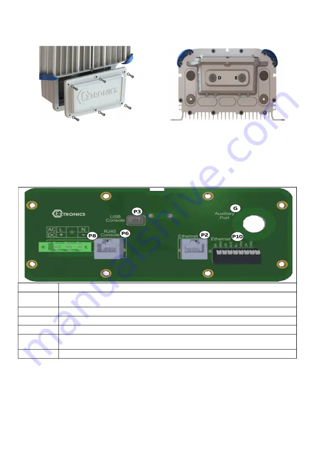
Remove all bolts to open the cover as shown in below figure [1].
2.
Add a suitable Ex-certified cable gland to the power cord (not included in the package). The
thread size in device is M20x1.5.
3.
Insert the power cable inside the housing through holes marked D or E, as shown in figure [2].
4.
Connect power cord wires to the green screw terminal block (P8).
5.
Connect the screw terminal block to the mating connector.
6.
Close the cover and tighten the screws.
7.
Connect to AC power.
Connectors
Description
P2
Ethernet port RJ45. Ethernet connection to Cassia X2000 gateway. by default connected to
P6.
P3
Not in use.
P6
Ethernet port RJ45. Ethernet connection to modem. By default connected to P2.
P8
Power input: 100 to 264 VAC
P10
Ethernet port, loose wires. Ethernet connection to Cassia X2000 gateway. Used as an
alternate connector for P2.
G
Auxiliary port or pressure test port.
[1]
[2]


