

Page 10
© 2023 ABB. All rights reserved.
CC1600SC55_QSG
Rev 4.0
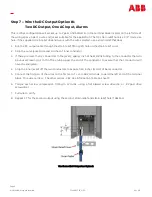
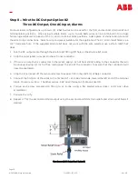
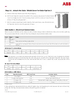
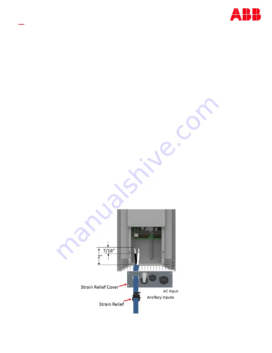
Step 8 –
Wire the DC Output Option #2
Three DC Output, One AC Input, Alarms
For Dual load configurations up to two (2) 8 AWG wires can be used for the first and second strain relief and
terminal block positions. When using multiple loads, up to two 16 AWG wires can be combined into a single
ferrule lug and placed into each of the (+) and (
-
) terminal block positions. Add a piece of shrink tubing to cover
the wire crimp connections. Select a wire and jacket suitable for the application. The DC strain relief holes are a
3/4”
trade size hole. If the supplied strain relief does not work with the wire selected, use a strain relief that
does.
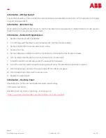
1.
Run the DC output cable through the strain relief fitting, left hole on the strain relief cover .
2.
Strip the outer jacket to reveal 2 inches of inner conductor.
3.
If there are more than 2 conductors in the jacket, apply 1 inch of heat shrink tubing to the conductor that will
be unused, leaving 1/2 inch of free tubing past the end of the conductor to assure that that conductor will
never be energized.
4.
Strip the inner jacket off the two conductors to expose 7/16 inches (11mm) of bare conductor.
5.
Connect the first pair of the wires to the first set of + and
-
48V terminals, toward the left end of the terminal
block. One wire c. The other carries
-
48V. See Information Table on sheet 10.
6.
Torque each screw compression fitting to 12 in
-
lbs. using a flat bladed screw driver, or #2 pozi drive
screwdriver.
7.
Pull wire to verify.
8.
Repeat 1
-
7 for the second and third output using the second and third strain reliefs and strain relief holes if
desired.
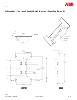
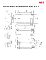
View shown with DC Output Panel Option #2


