


Page 11
© 2023 ABB. All rights reserved.
CC1600SC55_QSG
Rev 4.0
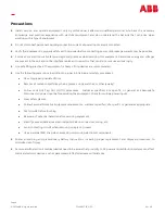
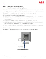
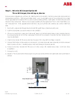
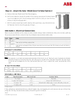
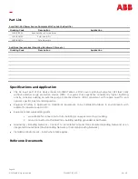
Step 9 –
Wire the Alarms
The Small Cell
-
48V Power Source provides two optional alarm contact
closures via an RJ
-
45 Jack and outdoor rated CAT
-
5 cable. See
Information Table on Sheet 9.
1.
Plug a shielded outdoor rated CAT
-
5 cable terminated with a
shielded RJ
-
45 termination into the alarm connector on the PWB.
2.
Run the other end of the wire through the smallest hole in the strain
relief.
3.
Terminate the CAT
-
5 cable with an RJ
-
45 connector.
4.
Pull wire to verify that the connection is latched.
Note: The shield in this cable is to be terminated to ground at both
ends. The ground termination on this end of the cable is made
through the shell. The RJ
-
45 connector used should have the
shield terminated to a shell that is like this one.
View Above shown using DC Output Option #1
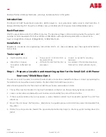
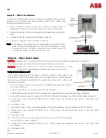
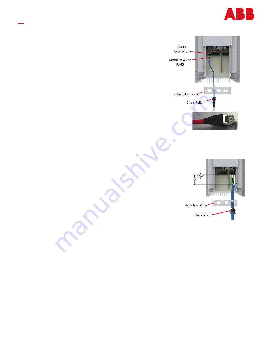
Step 10 –
Wire the AC Input
DANGER:
Shock Hazard –
Turn OFF and lock
-
out tag
-
out the AC source before making AC connections.
When connecting to AC mains, follow all local and national wiring rules.
CAUTION:
Ensure that wires do not come in contact with sharp or rough
surfaces that may damage insulation and cause a short circuit.
Verify all AC breakers are off!
The rectifier is designed for 10 AWG 3 conductor outdoor rated cable to be
terminated in the terminal block located on the right side of the wiring space.
Select a wire and jacket suitable for the application. Note: 15A or 20A circuit
protection is required.
1.
Run the AC input cable through the strain relief fitting, lower right hole on
the strain relief cover.
2.
Strip the outer jacket to reveal 2 inches of inner conductor.
3.
Strip the inner jacket off each of the 3 conductors to expose 7/16 inches (11mm) of bare conductor.
4.
Connect the ground wire first toward the left end of the terminal block. See Information Table on Sheet 9.
5.
Torque the screw compression fitting to 12 in
-
lbs. using a flat bladed screw driver, or #2 pozi drive
screwdriver.
6.
Pull wire to verify.
7.
Connect the Line 1 wire to the middle position of the terminal block. See Information Table on Sheet 9.
8.
Torque the screw compression fitting to 12 in
-
lbs. using a flat bladed screw driver, or #2 pozi drive
screwdriver.
9.
Pull wire to verify.
10.
Connect the line 2 or neutral conductor to the right end of the terminal block.
See Information Table on Sheet 9.
11.
Torque the screw compression fitting to 12 in
-
lbs. using a flat bladed screw driver, or #2 pozi drive
screwdriver.
12.
Pull wire to verify.
View Shown with DC Output Option #1


