
Page 15
© 2023 ABB. All rights reserved.
CC1600SC55_QSG
Rev 4.0
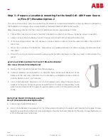
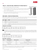
Information –
Lifting the Unit
The rectifier assembly is less than 80 lbs. and should have two installers to place the unit into position to the pole
or wall mounting bracket.
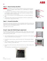
Information
–
External Icing
When external icing affects the access to the four hardware screws a plastic or rubber hammer can be used to
break the ICE to remove the securing screws.
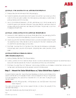
Information –
for Retrofit Applications
1.
Remove the solar shield if applicable.
2.
Turn off the power feeding the unit following Lock
-
Out Tag
-
Out procedures.
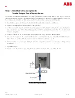
3.
Remove the ACCESS cover and disconnect wiring.
4.
Secure all wiring.
5.
Remove hardware holding the rectifier in position by removing the four hardware screws.
6.
Two installers shall remove the wall mounted or pole mounted unit.
7.
Install the retrofit unit and secure with the appropriate hardware.
8.
Install the electrical and dc output following removal using the installation procedure in reverse.
9.
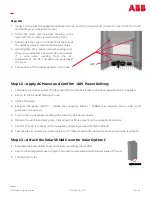
Close all openings and power the input and verify the LED is now green.
10.
Close all openings and secure the access cover.
11.
Replace the solar shield.
Information –
Touch Up Paint
Should any part of the unit coating be damaged, repaint using:
LVP Powder and Paints
RAL7035 Touch Up Paint –
Light Grey –
12
oz Spray Can.


