
Page 6
© 2023 ABB. All rights reserved.
CC1600SC55_QSG
Rev 4.0
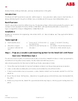
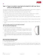
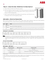
p/o Step 1 –
Pole Locations For use with Solar Shield Option 1
A.
Remove the pole mount bracket from the packaging.
B.
Select an elevation and orientation on the pole. Note: Wires must dress out of the
bottom of the unit when installed. Use the bracket as a template to locate holes. 2
primary holes are on 10 inch centers.
C.
Use 1/2 inch diameter hardware, 1.25 inch wide straps or 1/2 inch threaded rod to
attach the pole mount bracket to the pole. Torque lag bolts as specified on the bolt
corresponding to the pilot hole and material of the pole. Torque hdwr on 1/2 inch
threaded rod to 38 ft
-
lbs.
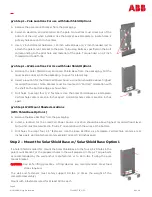
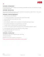
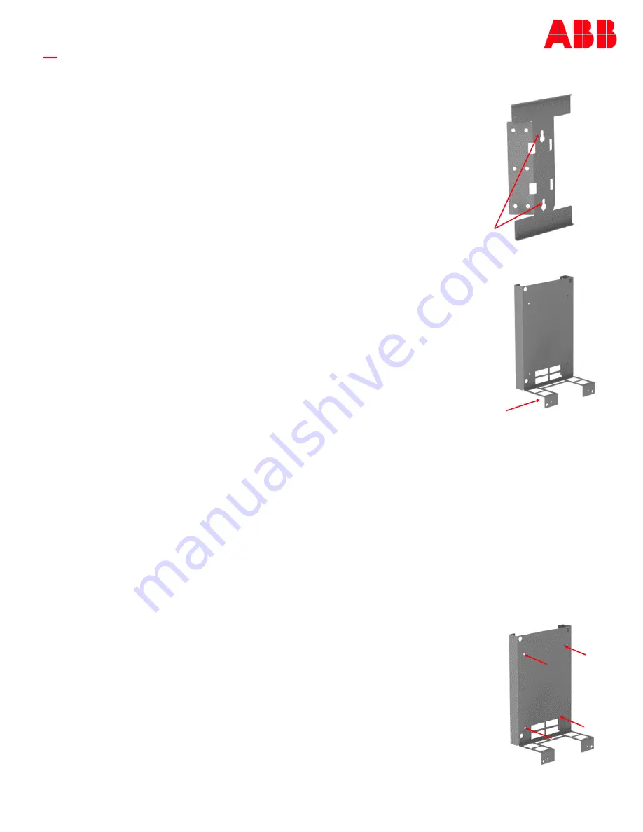
p/o Step 1 –
Wall Locations For Use with Solar Shield Option 1
A.
Remove the Solar Shield Cover and Solar Shield Base from the packaging. Put the
cover aside, or back into the packaging , to save for a later step.
B.
Select a location for the Small Cell Power Source. Location should be above highest
recorded flood level. Note: Bracket must be mounted in
“
Portrait
”
orientation with
the shelf on the bottom edge, as shown here.
C.
Drill holes to accept four
1/4”
fasteners. Use the Solar Shield Base as a template.
Vertical hole centers are 15.6 inches apart. Horizontal hole centers are 10.4 inches
apart.
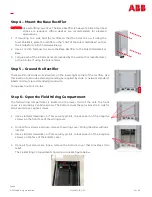
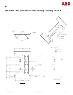
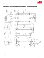
p/o Step 1 Wall Mount Shaded Locations
(With Shield Base Option 1)
A.
Remove the Base Rectifier from the packaging.
B.
Select a location for the Small Cell Power Source. Location should be above highest recorded flood level.
Note: Unit must be mounted in
“
Portrait
”
orientation with the wires at the bottom.
C.
Drill holes to accept four
1/4”
fasteners. Use the Base Rectifier as a template. Vertical hole centers are 12
inches apart. Horizontal hole centers are 8.87 (8 and 7/8 ) inches apart.
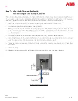
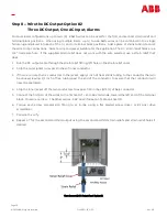
If a Solar Shield is called for, mount the Solar Shield Base to the four 1/4
-
20 holes in the
pole mount bracket, or the prepared holes in the wall prepared in Step 1. Torque bolts
as recommended by the wall anchor manufacturer, or to 65 in
-
lbs. if using the pole
mount bracket.
CAUTION:
Use safe lifting practices. Lifting devices are recommended. Steel toed
shoes required.
The wall and fasteners must safely support 90 lbs. (3 times the weight of the
completed assembly).
Mount with 4 fasteners rated for at least 50 lbs. each
Step 2 –
Mount the Solar Shield Base w/ Solar Shield Base Option 1


