
Page 8
© 2023 ABB. All rights reserved.
CC1600SC55_QSG
Rev 4.0
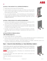
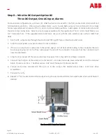
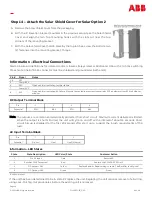
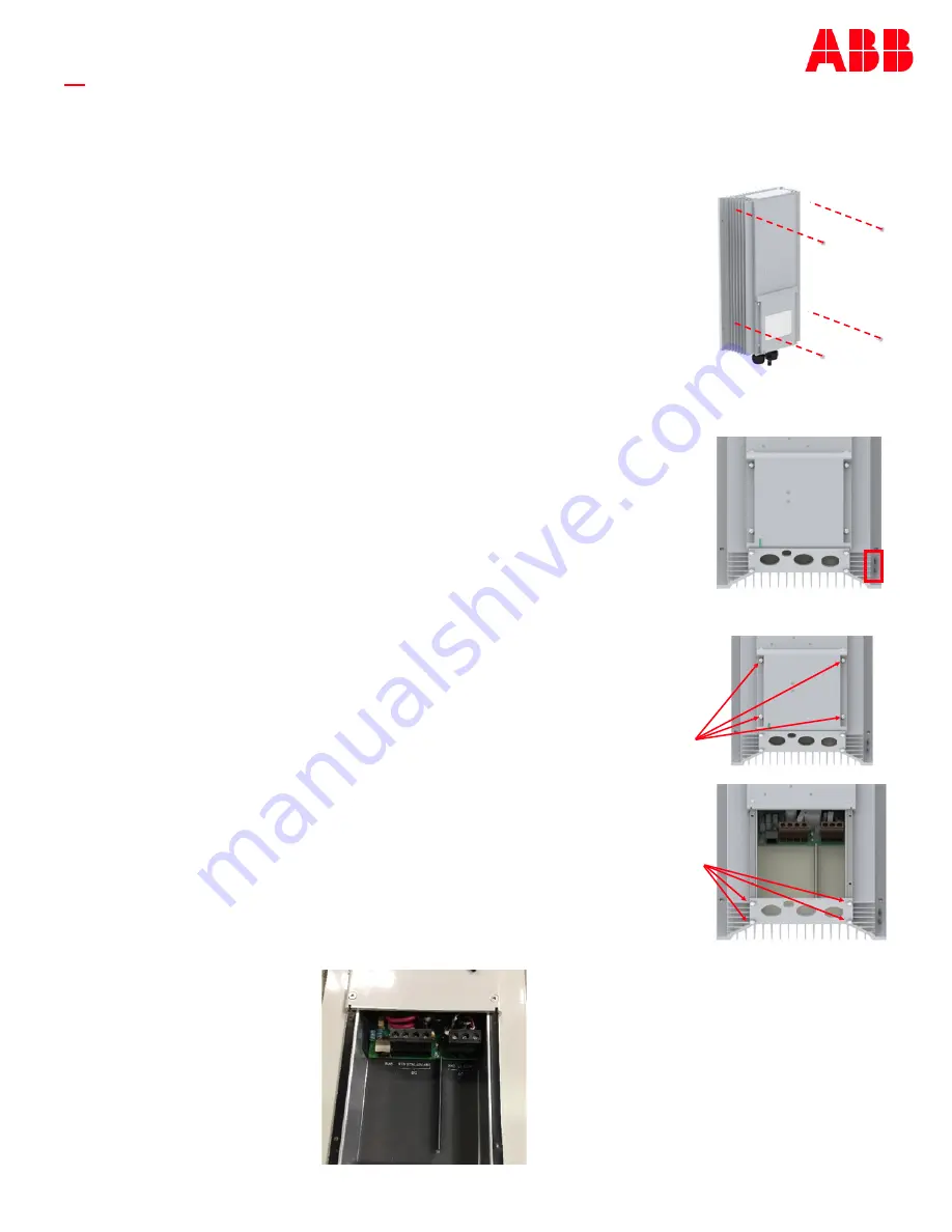
Step 4 –
Mount the Base Rectifier
CAUTION:
Use safe lifting practices. The Base Rectifier is heavy at 25 lbs. Steel toed
shoes are required. Lifting devices are recommended for elevated
applications.
1.
If mounting to a wall, hold the rectifier so that the holes line up. If using the
Solar Shield kit, place the rectifier on the
“
shelf of the solar shield base
”
so that
the 4 holes for 1/4 inch hardware line up.
2.
Use a 1/4 inch fastener to secure the Base Rectifier to the Solar Shield Wall or
Base.
3.
Torque each of the 4 bolts as recommended by the wall anchor manufacturer,
or to 65 in
-
lbs. if using the Solar Shield.
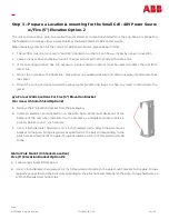
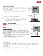
Step 5 –
Ground the Rectifier
There are #10
-
32 studs on 5/8 centers on the lower right corner of the rectifier. Use
this location to provide external grounding as required by code or network standard.
8 AWG minimum recommended ground wire.
Torque each nut to 26 in
-
lbs.
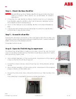
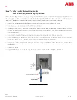
Step 6 –
Open the Field Wiring Compartment
The field wiring compartment is located on the lower third of the unit. The front
cover is secured by 4 captive screws. The bottom cover that provides strain relief is
also secured by 4 captive screws.
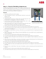
1.
Use a slotted screwdriver, or Torx security pin bit, to loosen each of the 4 captive
screws on the front face of the wiring cover.
2.
Once all four screws are loose, remove the wiring cover. Wiring chamber will look
like this.
3.
Use a slotted screwdriver, or Torx security pin bit, to loosen each of the 4 captive
screws on the face of the bottom cover.
4.
Once all four screws are loose, remove the bottom cover that provides strain
relief.
The Field Wiring Compartment should now look like figure below.


