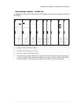
Default I/O diagram
Connectors of the CIO module and their default use is shown below.
Description
Terminal
Digital inputs/outputs
XDIO1…XDIO4
Monitoring (DI1) and control (DO1) (PWM output) of fan 1
DI1
11
1
1
1
2
1
3
2
1
2
2
2
3
3
1
3
2
3
3
4
1
4
2
4
3
DCOM
12
DO1
13
Monitoring (DI2) and control (DO2) (PWM output) of fan 2
DI2
21
DCOM
22
DO2
23
Monitoring (DI3) and control (DO3) (PWM output) of fan 3
DI3
31
DCOM
32
DO3
33
Monitoring (DI4) and control (DO4) (PWM output) of fan 4
DI4
41
DCOM
42
DO4
43
Digital inputs
XDI1, XDI2
CIO module miniature circuit breaker monitoring (0 = related warning or
fault is given, jumpered to 1 as default) (Parameter 206.50)
DI5
1
5
6
7
1
2
3
4
8
DCOM
2
CIO module fuse monitoring. 0 = related warning/fault is given. Parameter
206.51
DI6
3
DCOM
4
DI7: Not in use in the control program.
DI7
5
DCOM
6
DI8: Can be used for any purpose by using IEC program or general supervi-
sion function of the firmware. (0 = related warning or fault is given) (Para-
meter 206.53)
DI8
7
DCOM
8
Analog inputs
XAI1, XAI2
Reserved for fan temperature monitoring with an NTC thermal switch. No
software support currently.
AI1+
1
1
2
3
1
2
3
AI1-
2
SHIELD
3
Reserved for fan temperature monitoring with an NTC thermal switch. No
software support currently.
AI2+
1
AI2-
2
SHIELD
3
RS-485 communication link
X485
RS-485 communication link (I/O bus).
B
1
1
2
3
4
A
2
GND
3
SHIELD
4
I/O bus termination
TERM
Termination resistor
ON
OFF
Power supply
XPOW
20 Electrical installation
Summary of Contents for CIO-01
Page 1: ... ABB INDUSTRIAL DRIVES CIO 01 I O module and distributed I O bus User s manual ...
Page 2: ......
Page 4: ......
Page 42: ...42 ...
Page 44: ...44 ...

