background image

Device and diagnostics information

By clicking on the computer name at the top of the structure, you can see its device
information, such as the hardware and software versions, in the window on the right side
of the tree. By clicking on the OPC Server object name, corresponding device information
is displayed on the right. You can view device diagnostics information of the whole
subnetwork by clicking on the subnetwork object. To see the communication status or
diagnostic counter information of individual devices, click on the IED objects.

Single Line Diagram

3.5.

General about Single Line Diagram

3.5.1.

A Single Line Diagram (SLD) is a graphical user interface presenting process objects
(primary devices) of the substation as graphical symbols. HMI updates the SLD and the
substation and communication structures at regular intervals. A sample SLD is shown
in Figure 3.5.1-1

SLD_example.jpg

Figure 3.5.1-1 An example of the Single Line Diagram

13

COM 605 3.0

COM 600 Station Automation Series

1MRS756121

Operator's Guide

Summary of Contents for COM 600

Page 1: ...COM 600 Station Automation Series COM 605 3 0 Operator s Guide ...

Page 2: ......

Page 3: ...gle Line Diagram 13 3 5 2 Switch Device Control 14 3 5 3 Busbar coloring 15 3 6 Alarms 16 3 6 1 General about alarms 16 3 6 2 Monitoring and handling alarms 17 3 6 3 Acknowledging alarms 18 3 6 4 Filtering alarms 18 3 7 Events 19 3 7 1 General about events 19 3 7 2 Monitoring and handling events 19 3 7 3 Filtering events 20 3 8 Disturbance data upload 21 3 8 1 Disturbance recordings 21 3 9 User ma...

Page 4: ...3 11 1 Viewing measurements 28 Appendix 1 30 Single Line Diagram symbols 30 Index 35 4 1MRS756121 COM 600 Station Automation Series COM 605 3 0 Operator s Guide ...

Page 5: ...be used copied or disclosed only in accordance with the terms of such license Copyright 2006 ABB Oy All rights reserved Trademarks 1 2 ABB is a registered trademark of ABB Group All other brand or product names men tioned in this document may be trademarks or registered trademarks of their respective holders General 1 3 This manual provides thorough information on the Control and Monitoring Unit C...

Page 6: ...s are used for the name of a keyboard key if it is labeled on the keyboard For example press the ENTER key Lowercase letters are used for the name of a keyboard key that is not labeled on the keyboard For example the space bar comma key and so on Press CTRL C indicates that you must hold down the CTRL key while pressing the C key to copy a selected object in this case Press ESC E C indicates that ...

Page 7: ... communication node in the network e g protection relay Device Change of process data or an OPC internal value Normally an event consists of value quality and timestamp Event A physical IEC 61850 device that behaves as its own commu nication node in the IEC 61850 protocol Intelligent Electronic Device Series of standards specifications aiming at open connectivity in industrial automation and the e...

Page 8: ... Area Network LAN Single Line Diagram SLD Related documents 1 8 MRS number Name of the manual 1MRS756125 COM 600 3 0 User s Guide Document history 1 9 History Product revision Document version date Document created 3 0 A 16 10 2006 Document revised 3 0 B 22 1 2007 8 1MRS756121 COM 600 Station Automation Series COM 605 3 0 Operator s Guide ...

Page 9: ... a dedicated industrial computer without moving parts The products are configured using a separate engineering PC that is connected via the local area network LAN For more information refer to COM 600 User s Guide HMI functionality The features of HMI include a Single Line Diagram Busbar coloring lists of events and alarms disturbance data upload system supervision control of breakers and switches...

Page 10: ...e events list Help Shows the HMI help Logout Logs you out of the window Predefined user account 3 2 HMI has a predefined user account with administrator rights User name admin Password adminadmin When you log in for the first time as an administrator you have to change the password before you can proceed using HMI If you forget the new password restore the factory settings with the Management tool...

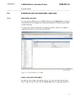
Page 11: ...an see the status of the IEDs in the substation structure If there is a problem in communication there is a red cross next to the IED substation_view jpg Figure 3 4 1 1 The substation view to HMI Alarm and event information By clicking on the voltage level and bay objects you can access their specific alarm lists To look at a list of events click on View Events above the Persisting Alarms list 11 ...

Page 12: ...re Communication structure 3 4 2 You can open the communication view of HMI by clicking on the Communication tab on the left The communication structure is displayed in the window on the left In the communication structure you can see the OPC Server communication channel objects and the IEDs You can see the status of the IEDs in the communication structure If there is a problem in communication th...

Page 13: ...subnetwork object To see the communication status or diagnostic counter information of individual devices click on the IED objects Single Line Diagram 3 5 General about Single Line Diagram 3 5 1 A Single Line Diagram SLD is a graphical user interface presenting process objects primary devices of the substation as graphical symbols HMI updates the SLD and the substation and communication structures...

Page 14: ... Also status information for example on the interlockings and selection state of the object are displayed To control a switch 1 Select the control direction by clicking Open or Close 2 Click Operate to activate the selection or Cancel to cancel the operation Note that some of the buttons may be disabled depending on the state of the switch It is possible to perform a forced cancel operation This i...

Page 15: ...ar sections are powered unpowered or in certain other states or which voltage level each busbar section has see Figure 3 5 3 1 Alternatively each voltage source or voltage source type can have a color that is used for sections they are connected to Busbar coloring can also be used to indicate if two or more voltage sources form a loop 15 COM 605 3 0 COM 600 Station Automation Series 1MRS756121 Ope...

Page 16: ...d sections 3 Voltage level based busbar coloring Different voltage levels have different colors 4 Voltage source based busbar coloring The coloring of powered sections depends on the voltage source Alarms 3 6 General about alarms 3 6 1 The Alarm List displays a summary of the present alarm situation of the supervised process Each alarm is presented as an alarm text line which describes the cause o...

Page 17: ... the menu bar at the top of the screen To view the alarms concerning a specific bay click on the appropriate object in the substation tree You can also filter the alarms concerning a specific voltage level or bay with the Filter function In the Persisting alarms list you can see active alarms The Fleeting alarms list displays a list of inactive unacknowledged alarms The alarm list is continuously ...

Page 18: ...st 2 Click Ack on the menu bar 3 To acknowledge all alarms at the same time click Ack all Filtering alarms 3 6 4 Filters can be used when you want to display only specific information To filter alarms 1 Click Filter in the toolbar of the Alarms view A window displaying the substation structure opens 2 Click on the object whose alarms you want to view Now the Alarms list displays only the alarms of...

Page 19: ...ring and handling events 3 7 2 You can monitor the events of the substation by clicking Events in the command bar at the top of the screen To monitor the events of specific bays click on the appropriate object in the substation tree The event list is updated automatically You can filter the events concerning a specific voltage level or bay with the Filter function You can stop the updating of the ...

Page 20: ...n To filter events 1 Click Filter in the toolbar of the Events view A window displaying the substation structure opens 2 Click on the object whose events you want to view Now the Events list displays only the events of the object that was selected and the objects below it 20 1MRS756121 COM 600 Station Automation Series COM 605 3 0 Operator s Guide ...

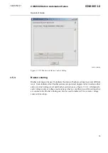
Page 21: ...ents voltages frequencies and binary signals and so on in a disturbance file before during and after a protection event These disturbance files can be copied to the COM 600 computer automatically if the function has been configured in CET You can see the list of disturbance recordings by clicking on Disturbances below the desired IED in the substation structure 21 COM 605 3 0 COM 600 Station Autom...

Page 22: ...n MS Excel You can also delete disturbance recordings from the COM 600 computer by clicking Delete User management 3 9 General about managing users 3 9 1 COM 605 has the following user levels Viewer Only allowed to view Operator Authorized to make operations Engineer Allowed to change IED parameters but no operation rights Administrator Full access The administrator can add users and define access...

Page 23: ... X X X view System supervi sion 1 Can change own password view view only Adding new users 3 9 2 The administrator can add users in the Add User window To add a new user 1 Click on the Users tab on the left 2 Select Add User 3 Type in a new user name The length of the user name can be 1 99 characters and it can only contain characters a z and 0 9 4 Type in a password and confirm it The length of th...

Page 24: ... user 1 Click on the Users tab on the left 2 Select the user you want to remove 3 Click Remove User and confirm by clicking OK To change a user s user group 1 Click on the Users tab on the left 2 Select the user whose user group you want to change 3 Click Change User Group 4 In the Change User s Group view select a new group from the drop down menu 5 Click Apply 24 1MRS756121 COM 600 Station Autom...

Page 25: ... 4 To change the password administrator 1 Click on the Users tab on the left 2 Select the user whose password you want to change 3 Click Change password 4 Type in a new password and confirm it 5 Click Apply 25 COM 605 3 0 COM 600 Station Automation Series 1MRS756121 Operator s Guide ...

Page 26: ...dministrator To change your own password 1 Click on the Settings tab on the left 2 Click Change password 3 Type in the old password 4 Type in a new password and confirm it 5 Click Apply 26 1MRS756121 COM 600 Station Automation Series COM 605 3 0 Operator s Guide ...

Page 27: ...eter information by clicking on Parameters below the desired IED in the substation structure if this functionality is supported by the IED In this view you can also change parameter settings Click the icon next to the parameter to open the corresponding help text for each parameter 27 COM 605 3 0 COM 600 Station Automation Series 1MRS756121 Operator s Guide ...

Page 28: ...valuea are incorrect a message Some settings are not in correct range is displayed and the background of the modified parameters turns red Type in values that are in the correct value range 4 To manually update the values click Refresh Values 5 After you have made all necessary changes click Disable Write Measurements 3 11 Viewing measurements 3 11 1 To view measurement information click on Measur...

Page 29: ...measurements bmp Figure 3 11 1 1 An example view of measurements 29 COM 605 3 0 COM 600 Station Automation Series 1MRS756121 Operator s Guide ...

Page 30: ...uit breaker Open position Circuit breaker Closed posi tion Circuit breaker Bad faulty position Disconnector Intermediate position Disconnector Open position Disconnector Closed position Disconnector Bad faulty position Use ANSI rep resentation Truck Intermediate position Use ANSI rep resentation Truck Open position Use ANSI rep resentation Truck Closed position 30 1MRS756121 COM 600 Station Automa...

Page 31: ...ec ondary winding below All composing elements exist as individual symbols Power Transformer with two Windings and no Tap Changer Primary winding on top Sec ondary winding below All composing elements exist as individual symbols Power Transformer with two Windings and Tap Changer Primary winding on top Sec ondary winding below left Tertiary winding below right All composing elements exist as indiv...

Page 32: ...larm symbol A Off state Alarm symbol A Acknow ledged state Blinking Alarm symbol A Unacknow ledged state Alarm symbol Led Off state Alarm symbol Led Acknow ledged state Blinking Alarm symbol Led Unac knowledged state Alarm symbol Star Off state Alarm symbol Star Acknowledged state Blinking Alarm symbol Star Unac knowledged state 32 1MRS756121 COM 600 Station Automation Series COM 605 3 0 Operator ...

Page 33: ...NSI IEC representation Description Bay Switch Indicator Station Switch Indicator IED face symbol IED screen symbol Complete IED symbol 33 COM 605 3 0 COM 600 Station Automation Series 1MRS756121 Operator s Guide ...

Page 34: ...34 ...

Page 35: ... 16 C communication structure 12 D device information 13 diagnostics information 13 disturbance recordings 21 E event information 11 events filtering 18 20 general 19 F functionality HMI 9 I IED information 12 M measurements viewing 28 35 COM 605 3 0 COM 600 Station Automation Series 1MRS756121 Operator s Guide ...

Page 36: ...agram general 13 symbols 30 substation structure 11 Switch Device Control 14 U users adding 23 change group 24 change password 25 managing 22 modifying properties 24 36 1MRS756121 COM 600 Station Automation Series COM 605 3 0 Operator s Guide ...

Page 37: ......

Page 38: ...1MRS756121 B 22 1 2007 ABB Oy Distribution Automation P O Box 699 FI 65101 VAASA FINLAND Tel 358 10 22 11 Fax 358 10 224 1094 www abb com substationautomation ...

Reviews: