background image

INSTRUCTION MANUAL

Command Series®

Strategic Loop Controller

Type SLC_2

PN25055

Summary of Contents for Command Series

Page 1: ...INSTRUCTION MANUAL Command Series Strategic Loop Controller Type SLC_2 PN25055 ...

Page 2: ...the process being controlled Some process upsets may cause injury or damage NOTICE The information contained in this document is subject to change without notice ABB Inc its affiliates employees and agents and the authors of and contributors to this publication specifi cally disclaim all liabilities and warranties express and implied including warranties of merchantability and fit ness for a parti...

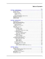
Page 3: ... REDUNDANT POWER SUPPLY WIRING 2 9 Grounding Procedures 2 9 AC SAFETY GROUND 2 9 DC SYSTEM COMMON GROUND 2 10 SINGLE POINT GROUNDING 2 10 Input Output Wiring 2 12 ANALOG I O WIRING 2 12 DIGITAL I O WIRING 2 14 Peer to Peer Communication Wiring 2 17 PRE OPERATING ADJUSTMENTS 2 18 Termination Board Switch Settings 2 19 ANALOG INPUTS 2 19 ANALOG OUTPUTS 2 20 DIGITAL INPUTS 2 21 Main Board Jumper Sett...

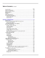
Page 4: ...s 4 8 Process Variable and Set Point Values 4 9 PV Alarm Values 4 10 Manual Control Upon Bad Quality of the Analog Inputs Outputs 4 10 Save or Abort Configuration 4 11 CUSTOM CONFIGURATION 4 12 Block Address 4 13 Function Codes 4 14 Specification List 4 16 Function Blocks 4 16 FIXED BLOCKS 4 16 USER DEFINED BLOCKS 4 16 CONFIGURATION UTILIZATION FACTORS 4 17 CONFIGURATION DATA REQUIRED 4 17 Station...

Page 5: ... 14 TUNE 5 15 PID Constants 5 15 Process Variable PV Alarms 5 17 D O CONTROL 5 18 AUXILIARY SWITCH OUTPUTS 5 19 CONTROLLER RESET 5 20 MODES OF OPERATION WHEN USING TYPE CTT TERMINAL 5 21 Execute 5 21 Configure 5 21 Error 5 22 SECTION 6 TROUBLESHOOTING AND DIAGNOSTICS 6 1 INTRODUCTION 6 1 CHECKING PROCESS CONTROL INTEGRITY 6 1 DIAGNOSTICS 6 3 ERROR MESSAGES 6 5 BROKEN ANALOG OUTPUT CURRENT LOOP 6 5...

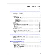
Page 6: ... 1 CONFIGURATION DRAWINGS A 1 Single Loop PID with Internal Set Point A 1 Single Loop PID with External Set Point A 2 Dual Loop Controller with Internal Set Point A 4 Dual Loop Controller with External Set Point A 6 Cascade Control A 8 Ratio Controller A 10 Fixed Block Locations A 12 APPENDIX B TYPE SLC SETUP WORKSHEETS B 1 INTRODUCTION B 1 APPENDIX C TYPE SLC CONFIGURATION WORKSHEETS C 1 INTRODUC...

Page 7: ...Digital Inputs in Nonisolated Mode 2 17 2 14 Digital Inputs in Isolated Mode 2 17 2 15 Digital Output Circuitry 2 18 2 16 Peer to Peer Communications Wiring Connections 2 19 2 17 Termination Board Switch Locations 2 20 2 18 Main Board Jumper Settings 2 22 2 19 Optional Input Board Jumper Settings 2 23 2 20 Jumper Settings Schematic 2 25 2 21 Serial Interface Board Jumper Settings 2 26 3 1 Setup Me...

Page 8: ...oard D 2 D 5 Options Board D 3 D 6 Serial Interface Board D 3 E 1 Screen Flowchart E 2 List of Tables No Title Page 1 1 Glossary of Terms and Abbreviations 1 8 1 2 Reference Documents 1 8 1 3 Nomenclature 1 9 1 4 Specifications 1 9 2 1 Termination Board Summary of Options Settings 2 21 2 2 Serial Port Pin Outs 2 23 2 3 Serial Interface Board J5 Settings 2 24 4 1 Analog Input Functions for Predefin...

Page 9: ... must be free of any hazardous materials acids alkalis solvents etc A Material Safety Data Sheet MSDS for all process liquids must accompany returned equipment Contact the factory for authorization prior to returning equipment Read these instructions before starting installation save these instructions for future reference Contacting the Factory Should assistance be required with any of the compan...

Page 10: ...and provides examples of screen displays Configuration Contains required user actions to establish and define the controller configuration This section also describes factory configurations in which all data can be entered through the faceplate of the controller via menu selections It also provides custom and modified factory configurations that require use of the Type CTT Configuration and Tuning...

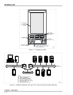
Page 11: ...rsonnel Should have a background in electricity and be able to recognize shock hazards Personnel must also be familiar with electronic pro cess control instrumentation and have a good understanding of trou bleshooting procedures PRODUCT OVERVIEW This section contains functional physical and communication charac teristics of the controller Functional Description The Type SLC Strategic Loop Controll...

Page 12: ...ONITOR Numerically displays all I O and four function block outputs It also includes a STATUS menu item that includes diagnostics and software revision levels ALARM SUM Provides clear concise alarm descriptions BYPASS Locks in a manual override capability on both analog outputs TUNE Provides quick access to the PID tuning parameters and to adjustable alarm settings D O CTRL Provides faceplate cont...

Page 13: ...d marked to prevent possible customer connection errors Type SLC22_ controllers have an optional input board for low level or frequency pulse inputs It connects to P6 on the main board Type SLC_21 controllers have a serial interface board that allows termina tion board access to the serial interface at the rear of the controller The serial interface board connects to P7 and P8 on the main board Th...

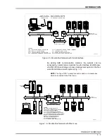
Page 14: ...ximately 600 to 700 real points a mix of analog and digital per second The network can contain up to 32 address able modules controllers enabling over 60 loops of control Controllers on the network can be linked to a PC through the stand alone Type CIC01 Computer Interface Command Module Fig 1 4 Tools such as the ABB engineering work station software and LAN 90 Process Control View PCV can be used...

Page 15: ...DOWN PUSHBUTTONS Figure 1 4 Module Bus Network with Type CIC01 Computer Interface Command Module PC TP80408A EXPANSION BUS UP TO 30 CONTROLLERS MODULE BUS CBC CLC CTT CSC SLC SLC SLC CLC CIC CBE CBE MODULE BUS 610 M 2 000 FT MAX LEGEND CBC BATCH COMMAND CONTROLLER CBE MODULE BUS EXTENDER CIC COMPUTER INTERFACE COMMAND CLC LOOP COMMAND CONTROLLER CSC SEQUENCE COMMAND CONTROLLER CTT CONFIGURATION AN...

Page 16: ...RFACE ADAPTER SLC STRATEGIC LO OP CONTRO LLER T02141A UP TO 30 CO NTRO LLERS CLC PC SIA FRONT ACCESS SERIAL INTERFACE CO NNECTION SERIAL CONN ECTION FROM REAR O F CO NTROLLER TO PC DOES NOT REQUIRE SIA CLC CSC SLC SLC SLC SLC 610 M 2 000 FT M AX CBE CBE CTT CBC M ODULE BUS EXPANSIO N BUS M ODULE BUS Figure 1 6 Module Bus Network with Plant Loop PC TP80430A EXPANSION BUS UP TO 30 CONTROLLERS MODULE...

Page 17: ... control algorithm and an analog output driving a final control element Module Bus Peer to peer communication link used to transfer information between intelligent modules within a process control unit Ratio Station An analog control station configuration that maintains a ratio between two variables The ratio of an externally generated wild variable times the controlled variable becomes the set po...

Page 18: ...mper selectable with the option board installed 2 Use of the option board does not change the I O count of the controller The optional input board contains circuitry for a frequency pulse input and 2 temperature modules for direct temperature inputs Hardware jumpers refer to Appendix D and menu options permit selecting the function of DI3 AI3 and or AI4 Digital input DI3 may be used as a digital o...

Page 19: ... European Std DIN alpha 0 00385 U S Ind Std SAMA alpha 0 00391 120 Ω Ni Chem Pure alpha 0 00672 NOTE RTD input may be affected up to 10 by RFI at 30 45 MHz and 75 85 MHz 20 to 80 mV linear Frequency pulse input Quantity available Input type Valid high input range 24 V 5 V Valid low input range 24 V 5 V Maximum frequency Minimum pulse width 1 in place of standard digital input DI3 5 or 24 VDC opto ...

Page 20: ...ower interrupt Main board fuse F1 2 5 A 250 V external DC power interrupt Configuration execution rate Factory default 4 scans sec Faster rates can be selected by the user Execution rate is dependent on configuration size NVRAM memory 16 kbytes nonvolatile static RAM Serial communication Serial protocol ABB module bus bi directional 2 wire 83 kbaud RS 232 C 9 pin serial interface 1 2 through 19 2 ...

Page 21: ...s Order by nomenclature Type CLB01 Module bus extender Increases module bus distance from 10 meters to 610 meters 33 ft to 2 000 ft Order by nomenclature Type CBE01 ESD field service kit For personnel working on equipment containing static sensitive devices Includes static dissipative work mat ground cord assembly alligator clip and wrist bands Order by part no 1948385_1 Retrofit mounting kit Type...

Page 22: ...re selectable SPECIFICATIONS SUBJECT TO CHANGE WITHOUT NOTICE NOTE Temperature accuracy shown does not include mV to degrees conversion accuracy Testing performed with function code 182 S12 7 Shaded area of available measuring range cannot maintain accuracy stated Figure 1 7 Instrument Accuracy and Available Measuring Ranges for Direct Temperature Inputs Fahrenheit Scale Table 1 4 Specifications c...

Page 23: ...ailable Measuring Ranges for Direct Temperature Inputs Celsius Scale 100 PLATIN UM EURO PEAN STD DIN ALPHA 0 00385 Ω 100 PLATIN UM U S STD ALPHA 0 00391 Ω T02139A 120 NICKEL ALPHA 0 00672 Ω TYPE J TYPE K TYPE E TYPE T TYPE S TYPE R TYPE N 1500 C 1000 C 500 C 0 C 1600 1400 1300 1200 1100 900 800 700 600 400 300 200 100 100 200 1700 1800 0 20 C 0 34 C 0 36 C 0 6 C 0 7 C 0 5 C 1 2 C 1 0 C 3 8 C 3 9 C...

Page 24: ...e filed with the transporta tion company responsible Also the nearest ABB sales office should be notified as soon as possible Carefully inspect the packing material before discarding it to make certain that all mounting equipment and any special instructions or paperwork have been removed Careful handling and installation will insure satisfactory performance of your unit Use the original packing m...

Page 25: ...ounding wrist strap that is connected to the station or to a good ground point at the field site 4 Do not allow clothing to make contact with static sensitive devices Most clothing generates static electricity 5 Avoid touching edge connectors and components 6 Avoid partial connection of static sensitive devices Static sensi tive devices can be damaged by floating leads especially the power supply ...

Page 26: ...Asso ciation CSA and CSA NRTL nationally recognized test lab Refer to Table 1 4 Refer to the Installing a 4 20 mA Transmitter in a Hazardous Location application guide Table 1 2 for specific guidelines when using an instrument in a Division 2 hazardous location Radio Frequency Interference Most electronic equipment is influenced by radio frequency interfer ence RFI Caution should be exercised with...

Page 27: ...emble the mounting brackets on the housing making certain that the bushing in the mounting bracket assembly is positioned in the mounting hole on the housing Fig 2 1 Tighten the bracket screws until the housing is secure in the panel 3 If installing multiple units repeat Steps 1 and 2 until all units are installed WIRING REQUIREMENTS Conduit knockouts inch and inch are located at the rear of the c...

Page 28: ...LERS FOR CE MARK APPROVED T02171A DIMENSIONS MILLIMETERS INCHES KNOCKOUT FOR 3 4 IN CONDU IT PANEL THICKNESS SEE NOTE 3 SEE NOTE 1 MIN A A MO UNTING BRACKET PANEL CUTOUT DIMENSIONS METRIC A 71 6 x NO O F UNITS 3 6 ENGLISH A 2 82 x NO OF UNITS 0 14 FRONT VIEW REAR VIEW COVER REM OVED MINIMUM CLEARANCE MAXIMUM TO RQUE 4 NM 30 IN LB FRO NT PLATE RETAINING SCREW 24 VDC INPU T 120 220 240 VAC INPUT TER...

Page 29: ...intain system safety and accuracy The cover prevents operator access to parts which may cause an ignition capable arc acts as an electrical shield to reduce the effects of EMI RFI and helps minimize temperature gradients It is important that the cover be securely mounted during normal use Power Wiring Use the following procedures to complete the wiring and terminations for the controller DC POWER ...

Page 30: ...I3 PWR DI3 DI3 CO M 24 V IN CO M S1 S1 AI1 AI2 AI3 AI4 AO1 AO2 DI1 DI2 DI3 AI1 AI2 AI3 AI4 AO1 AO2 DI1 DI2 DI3 V V V V I I ISO ISO ISO V V V V I I ISO ISO ISO I I I I V V NO N NO N NO N I I I I V V NO N NO N NO N ON OFF ON OFF POW ER SW ITCH POW ER SWITCH S3 S3 1 2 3 4 5 6 7 8 9 10 11 12 13 14 15 16 17 18 19 20 1 2 3 4 5 6 7 8 9 10 11 12 13 14 15 16 17 18 19 20 20 19 18 17 16 15 14 13 12 11 10 9 8...

Page 31: ...em should not be powered from a transformer which also powers large motor loads over 5 horsepower or any other type of equipment which will generate line voltage surges and sags 2 Remove terminal block TB3 from the termination board 3 Connect the specified line voltage 120 220 or 240 VAC 50 or 60 Hz to terminal block TB3 1 L1 H on the termination board 4 Connect the neutral conductor to terminal T...

Page 32: ... are not a hazard including under fault conditions to operation and service personnel The Type SLC controller provides for a connection of an AC safety grounding conductor customer supplied at TB3 4 on the termi nation unit NOTE Because of the prevailing differences in soil conditions throughout the world and differences in acceptable practices it is not within the scope of this instruction to des...

Page 33: ...s link the system commons are also con nected by the module bus Therefore read and follow the instructions for single point grounding SINGLE POINT GROUNDING Single Controllers Single point grounding of the Type SLC controller provides an analog and digital DC grounding system free of circulating currents Jumper W106 on the power supply board Fig 2 3 connects the DC system common to the AC groundin...

Page 34: ... NLY USING ONE OF THE TWO SCREW S LOCATED IN UPPER CO RNERS O F TER MINATIO N UNIT M INIM UM WIRE SIZE FOR THESE CO NNEC TIONS IS NO 18 AW G W IRE 5 TB3 2 AND TB3 4 ARE AC SAFETY G RO UNDS AC SAFETY GROUND BUS IS TO BE CONNECTED TO G RO UNDED CIRCUIT O F W IRING SYSTEM OF SITE USING NO 6 AW G W IRE TYPICAL TB1 TB2 AI1 PW R AI1 AI1 AI2 PW R AI2 AI2 AI3 PW R AI3 AI3 AI4 PW R AI4 AI4 AO1 AO1 AO2 AO2 ...

Page 35: ... board NOTE The field end of the shield should not be connected to a ground Conduit is recommended for the field portion of the run Wherever practical it is recommended that trays containing analog signals be devoted exclusively to that use Conduit containing analog sig nals should cross power lines etc at right angles and remain perpendicular for at least ten times the diameter of the crossed ele...

Page 36: ...W R AI3 AI3 AI4 PW R AI4 AI4 AO1 AO1 AO2 AO2 M OD BUS COM M OD BUS COM DO1 DO1 DO2 DO2 DO3 DO3 DO4 DO4 DI1 PWR DI1 DI1 DI2 PWR DI2 DI2 DI3 PWR DI3 DI3 COM 24 V IN COM S1 AI1 AI2 AI3 AI4 AO1 AO2 DI1 DI2 DI3 V V V V I I ISO ISO ISO I I I I V V NON NON NON ON OFF POW ER SWITCH S3 1 2 3 4 5 6 7 8 9 10 11 12 13 14 15 16 17 18 19 20 20 19 18 17 16 15 14 13 12 11 10 9 8 7 6 5 4 3 2 1 1 1 2 2 3 3 4 4 T B ...

Page 37: ... the termination board NOTE The field end of the shield should not be connected to a ground 4 Maximum wire gauge for the plug in connectors on the rear of the controller is 14 AWG Figure 2 7 Unpowered or Field Powered Four to 20 Milliamp Analog Input Figure 2 8 Single Ended Voltage Input TERMINAL BLOCK TB1 XMTR AI PWR 24 V 150 3 W Ω S1 7 8 9 10 CLOSED 250 3 W Ω FIELD TERMINATION BOARD MAIN BOARD I...

Page 38: ... to the termination board either signal or power and a 75 degrees Centigrade 167 degrees Fahrenheit minimum rating Wir ing must be in accordance with the National Electrical Code Figure 2 9 Differential Voltage Analog Input AI PWR TERMINAL BLOCK TB1 XMTR 24 V 150 3 W Ω S1 7 8 9 10 OPEN 250 3 W Ω FIELD TERMINATION BOARD MAIN BOARD INPUT CIRCUITRY TP80421B MUX Figure 2 10 Thermocouple Millivolt and ...

Page 39: ...ure 2 12 Analog Output in Voltage Mode 24 V S1 5 6 OPEN TERMINATION BOARD ACOM TB1 250 Ω MAIN BOARD OUTPUT CIRCUITRY TERMINAL BLOCK TP80006B FINAL ELEMENT AO AO 24 V AO AO S1 5 6 CLOSED TERMINATION BOARD TP80007B ACOM 250 Ω TB1 FINAL ELEMENT MAIN BOARD OUTPUT CIRCUITRY TERMINAL BLOCK ...

Page 40: ...res insulated with low leakage insulation materials Figure 2 13 Digital Inputs in Nonisolated Mode Figure 2 14 Digital Inputs in Isolated Mode 5 V TERMINATION BOARD TP80423B FIELD 24 V MAIN BOARD INPUT CIRCUITRY S1 1 2 3 CLOSED TERMINAL BLOCK TB2 DI PWR 5 V TERMINATION BOARD TP80424B FIELD 24 V MAIN BOARD INPUT CIRCUITRY S1 1 2 3 OPEN TERMINAL BLOCK TB2 24 V EXTERNAL DI PWR ...

Page 41: ...ule Bus Extenders must be used if the module bus length is more than 10 meters 32 8 feet or where ground potentials cannot be avoided Total maximum module bus dis tance with the Type CBE01 extender is 610 meters 2 000 feet Refer to Figures 1 4 1 5 and 1 6 for location of the module bus extenders in the communication loop NOTE The 1 8 meter 6 foot cord of the Type CTT Configuration and Tuning Termi...

Page 42: ...TING SCREW T02138A TB1 TB2 AI1 PW R AI1 AI1 AI2 PW R AI2 AI2 AI3 PW R AI3 AI3 AI4 PW R AI4 AI4 AO1 AO1 AO2 AO2 MO D BUS COM MO D BUS COM DO1 DO1 DO2 DO2 DO3 DO3 DO4 DO4 DI1 PW R DI1 DI1 DI2 PW R DI2 DI2 DI3 PW R DI3 DI3 COM 24 V IN COM S1 AI1 AI2 AI3 AI4 AO1 AO2 DI1 DI2 DI3 V V V V I I ISO ISO ISO I I I I V V NON NON NON ON OFF POW ER SW ITCH S3 1 2 3 4 5 6 7 8 9 10 11 12 13 14 15 16 17 18 19 20 2...

Page 43: ...t 3 Place the switch in the off position for a current output Figure 2 17 Termination Board Switch Locations SW ITCH S1 AN ALOG INPUT OPTIONS AN ALOG OUTPUT OPTIONS DIGITAL INPUT OPTIONS SEE NOTE NOTE SW ITCH S1 IS INSTALLED UPSIDE DOW N SW ITCH S3 EXTERNAL POW ER SUPPLY ON OFF SWITCH 1 2 3 4 5 6 7 8 9 10 TB1 SW 3 OFF ON P5 P3 R9 R10 S1 TB3 TB4 TB2 20 19 18 17 16 15 14 13 12 11 11 12 13 14 15 16 1...

Page 44: ...Termination Board Summary of Options Settings1 Option Control Setting2 Description Sample Switch Configuration Figure No Analog input 1 S1 10 On Current input Figures 2 6 through 2 10 Off Voltage input Analog input 2 S1 9 On Current input Off Voltage input Analog input 3 S1 8 On Current input Off Voltage input Analog input 4 S1 7 On Current input Off Voltage input Analog output 1 S1 6 On Voltage o...

Page 45: ... interface is intended for connection to a nine pin RS 232 C serial port The serial port on the PC or other communication device must have the pin outs listed in Table 2 1 Figure 2 18 Main Board Jumper Settings J1 J2 J1 J2 J1 J2 DI3 DI3 DI3 DI3 1 2 3 1 2 3 STANDAR D INPUT DEFAU LT DEFAU LT ON LY WITH OPTIO NAL INPUT BOARD ON LY WITH OPTIO NAL INPUT BOARD RIBBO N CABLE TO OPERATOR INTERFACE BOARD F...

Page 46: ... controller A nine pin RS 232 C cable provides for connection of the assembly to a PC and a second cable connects the assembly to the five pin connector on the front of the controller An LED on the assembly indicates when the serial interface is transmitting Figure 2 19 Optional Input Board Jumper Settings Table 2 1 Serial Port Pin Outs Pin Signal 1 DCD 2 RXD 3 TXD 4 DTR 5 SG 6 DSR 7 RTS 8 CTS 9 R...

Page 47: ...by the controller These sig nals are optically isolated Use of this board allows access to the serial interface at the nine pin RS 232 C connector on the termination board P5 The jumpers on the serial interface board allow connection to either data terminal equipment DTE or data communication equipment DCE The factory defaults are for the DTE connection that is required for CCAD01 Command CAD Conf...

Page 48: ...TS 2 25 Figure 2 20 Jumper Settings Schematic 12 VDC DCD T02251A DSR DTR RI ACOM SG J4 J1 J2 J3 J5 TXD T1 RXD RXD T1 TXD RTS T1 RTS CTS T1 CTS P5 2 P5 3 P5 7 P5 8 P5 1 P5 6 P5 4 P5 9 P5 5 5 1 3 4 2 7 6 8 12 10 9 3 2 1 3 2 1 3 2 1 3 2 1 11 ...

Page 49: ... Interface Board Jumper Settings DTE NO HANDSHAKING DCE NO HANDSHAKING DTE HANDSHAKING DCE HANDSHAKING J4 J1 J2 J3 J5 J5 J5 J5 J5 T02176A 1 3 4 2 1 3 4 2 1 3 4 2 1 3 4 2 6 6 6 6 5 5 5 5 8 8 8 8 7 7 7 7 11 9 10 12 11 9 10 12 11 9 10 12 11 9 10 12 J4 J1 J2 J3 1 2 3 ...

Page 50: ...re bracketed on the screen illustration or are located in the right margin The graphics of the screens presented are close representations but data may vary in size and position Pushbutton functions are shown in Figure 3 1 Single Function Pushbuttons The three marked pushbuttons at the bottom of the faceplate are sin gle function keys Controls cursor movement changes selection choices on screens a...

Page 51: ...te of the audible alarm associated with loop 1 bypass direction and process display type for loop 1 LOOP 2 Allows changing the same parameters for loop 2 MODBUS ADDR Gives the option to set the software module bus address Factory default is 2 D O LOCKOUT Allows individually locking or unlocking each digital output from face plate control SECURITY Allows changing the security passwords and the pass...

Page 52: ...ing a factory configuration or developing a custom configura tion Make certain that your selections provide a process condition that is unlikely to cause injury or equipment damage if a problem occurs NOTES 1 A continuous push of or will accelerate the ramping func tion during procedural steps 2 The following procedure is presented for single loop controllers Whenever loop 1 AO1 is referenced repe...

Page 53: ...name of the units of the values The maximum number of characters allowed is five Valid characters are A to Z 0 to 9 hyphen and PV EU SP EU 3 Press or until PV EU is highlighted Press Select the process variable engineering units Press or until the character appears and then press the soft key below or to move the cur sor to the next position Once the engineering unit characters have been entered p...

Page 54: ... the soft key below NEXT SCRN and the loop options menu will appear LOOP OPTIONS Station Power Up This specification is the initial mode of the control loop after start up The station will be in bypass mode for the configurable start up period after power up reset switch to execute mode After the start up period expires the mode is as indicated by this specification unless overrid den When configu...

Page 55: ...his option determines what value the analog output is set to when the unit has failed If a failure should occur the controller will go into bypass mode Valid selections are HIGH LOW and LAST The high value is 5 25 VDC or 21 milliamps while the low value is 0 75 VDC or three milliamps Selecting LAST maintains the last valid analog out put value until the unit is powered down reset switch to execute...

Page 56: ...ption must be consistent with the configuration to support ATC ATO final control element in the main board Refer to Reverse Acting Final Control Elements in Section 4 for supporting logic BYP ACTION 5 Press or until BYP ACTION is highlighted Press To select the action when the controller is in bypass mode press or to select DIR or REV Press 6 Press the soft key below NEXT SCRN to continue Process ...

Page 57: ...troller will be on the same module bus MODBUS ADDR 1 From the setup menu press or until MODBUS ADDR is highlighted Press Set the module bus address for the controller by pressing or until the correct value appears Figure 3 2 Process Display Selections PV TRK 219 0 ALM CF HR x1000 FIC 200 PV SP 300 225 150 75 0 OPN CLS H L INT L2 AUT PV TRK 219 0 ALM CF HR x1000 FIC 200 PV SP 300 225 150 75 0 OPN C...

Page 58: ...reen LOCK is used to designate that the digital output has been locked by this option while LOCK designates that it has been locked by the configuration D O LOCKOUT 1 From the setup menu press or until D O LOCKOUT is highlighted Press Press or until DO 1 is highlighted Press to toggle between LOCK and UNLOCK Repeat this step to set all the digital outputs Press one of the soft keys and the soft ke...

Page 59: ...high lighted Press The security password screen will appear If it is desired to set up a security function determine a password for both master and technician MASTER should be highlighted Press again The soft key menu will appear and a cursor will appear on the left side of the password to be entered 2 Choose any ASCII character for the password Maximum charac ters for the password are three Press...

Page 60: ...ct Repeat this step to assign the security levels for the rest of the functions Once complete press any soft key and the soft key menu will appear Press SET MENU and the Confirm Set tings screen will appear Press the soft key below YES or NO Return to the setup menu and continue L1 MAN L2 MAN SETUP Confirm Settings MASTER AAA TECHNICIAN AAA L1 MAN L2 MAN SETUP Enter New Security Levels BYPASS é TU...

Page 61: ...d is installed the option board screen will appear and FREQUENCY is highlighted Press FREQUENCY This option determines whether digital input three is to be used as a frequency input This feature is only available if the option board is installed and the main board jumpers have been properly positioned L1 MAN L2 MAN SETUP OPTION BRD FP SW LOOP 1 FP SW LOOP 2 AUX SW LBLS AMBIENT TMP TREND LOOP 1 TRE...

Page 62: ...list Press or to scroll through the input list When the correct input is highlighted press Set the engineering units EU in degrees Celsius or Fahrenheit To set the resistance L W RES OHMS press A new soft key menu will appear and a cursor will be under the first zero to the right of the decimal Use the soft keys below and to position the cur sor and press or to establish the correct value When com...

Page 63: ... a temperature input NOTE A 0 to 60 mV source accurate to 0 01 is required for cali bration if mV or thermocouple was selected in setup If RTD was selected in setup calibration requires a precision 300 ohm resistor with 0 1 accuracy or better The screens in the following CAL AI3 and CAL AI4 text are for millivolt or thermocouples The values and text on the screens will automatically change if RTD ...

Page 64: ...ed the controller will take a reading of the 0 mV source Once the reading is taken the screen will change to say connect 60 mV between AI3 and AI3 Press the soft key below CAL Once the reading is complete the controller will return to the options menu CAL AI4 Repeat Steps 5 and 6 for AI4 if required After calibration is complete a short message will appear CHANNEL CAL OK PRESS ANY KEY TO CONTINUE ...

Page 65: ...itch Normally the soft key menu item in that position displays PREV SCRN Selecting this option disables the PREV SCRN function for this particular loop With the highlight on Use press and a YES NO box will appear By selecting YES with or this soft key menu display can be changed to designate a switch Two four character tags can be desig nated to show the switch as being on or off This option is av...

Page 66: ...nges to this switch state after setup is complete are done from the main menu under AUX SWITCH Refer to Section 5 for additional information Press to confirm Press the soft key below PREV SCRN to continue and return to the options setup menu Ambient Temperature This option allows entering the ambient temperature at the terminals to set the cold junction compensation conversion factor This proce du...

Page 67: ... numeric readout of all three values as well as mode and alarm indications These trend screen features allow maintaining complete process control while graphically viewing the dynamics of the process over time TREND LOOP 1 TREND LOOP 2 14 From the setup options menu press or to highlight TREND LOOP 1 or TREND LOOP 2 Press The SET LOOP screen appears 15 Press or to highlight the function Press The ...

Page 68: ... framing to match the values required by the software being used 1 From the setup options menu press or until Serial Port is highlighted L1 AUTO L2 AUTO SET LOOP 1 TREND ON OFF PV ON OFF SP ON OFF CO ON OFF RATE 0 5 S see menu Rate Pull Down Menu 0 5 S 10 S 1 0 S 1 5 S 180 S 2 0 S 4 M 2 5 S 5 M 3 0 S 6 M 3 5 S 7 M 4 0 S 8 M 4 5 S 5 S 29 M 6 S 30 M 7 S 40 M 8 S 50 M 9 S 60 M PREV SCRN PROC DSPL TRN...

Page 69: ... and then press 6 To set the data framing press or until PARITY is high lighted 7 Press and the data framing list appears 8 Press or until the proper value appears and then press DISPLAY BRIGHTNESS The display brightness may be user controlled by selecting this menu option There are 15 levels of screen brightness allowed A lower set ting will prolong the life of the display BRIGHTNESS 1 From the m...

Page 70: ...rror occurs in the controller A process failure occurs for which a trip block function code 32 has been selected This might be specified for critical inputs or interlocks or violations of critical cross limits L1 MAN SETUP LOOP 1 LOOP 2 MODBUS ADDR D O LOCKOUT SECURITY DIAGNOSTIC OPTIONS BRIGHTNESS L1 MAN SETUP MAIN MENU PROC DSPL ESC PROC DSPL SAVE 1 ADJUST BRIGHTNESS Ø WARNING The analog and dig...

Page 71: ...e D O LOCKOUT screen Setting any digital output to the lock mode will disable face plate control from the main menu D O CONTROL screen For those users with custom or modified factory configuration direct digital output control can be issued through the configuration proce dures Refer to D O LOCK in Section 4 for additional information Refer also to function code 231 S12 through S16 in the Function...

Page 72: ...om mended to fill in the worksheets prior to starting a configuration proce dure All the data will then be available to make the entries Common PID configurations that will cover most applications can be directly entered from the controller faceplate refer to FACTORY CONFIGURATION If a complex or customized configuration is required for your applica tion refer to CUSTOM CONFIGURATION To use a fact...

Page 73: ...ble highlighted to change its values Multi Function Soft Keys Three unmarked soft keys directly below the display are multi function keys Their specific function is defined by the graphics and will vary depending on the screen displayed When no soft key menu is dis played directly above the soft keys touching any of these soft keys will display a soft key menu Once this soft key menu is displayed ...

Page 74: ...rations Single loop PID internal set point Single loop PID external set point Dual loop PID internal set point Dual loop PID external set point Cascade Ratio These drawings will provide an insight as to how the six factory con figurations are developed Entering a Factory Configuration NOTE It is not required to initialize before entering a configuration A series of user friendly display screens pr...

Page 75: ...er is not in bypass mode a warning screen will appear If the controller is already in the bypass mode the ADD MODIFY screen will appear 4 To start on the configuration process the controller must be in the bypass mode Press the soft key below BYP to place the controller into the bypass mode To view the screens press the soft key below VIEW ONLY to read only NOTE In view mode default values will ap...

Page 76: ...n will appear The screen display is dependent on the selection made in Step 7 of Entering a Factory Configuration For SINGLE PID and SING PID EX LOOP 1 For DUAL PID and DUAL PID EX LOOP 1 and LOOP 2 For CASCADE PRIMARY and SECONDARY For RATIO WILD VAR and CTRL LOOP 2 Press or to select the control loop Press Select SAVE or QUIT L1 BYP CONFIGURE ADD MODIFY INITIALIZE Current Config CUSTOM L1 BYP CO...

Page 77: ... 00 the range is 100 000 00 to 100 000 00 engineering units EU Thermocouple and RTD inputs do not require the zero specification 1 The analog input screen will appear To set AI ZERO press or When highlighted press Use or to enter the correct value for AI ZERO The default value is 0 00 The range is 100 000 00 to 100 000 00 engineering units EU Press Table 4 1 Analog Input Functions for Predefined C...

Page 78: ...lt value if an error has been made and it needs to be entered again SQRT 3 Press to proceed to SQRT square root Square root is used to convert differential pressure into flow units A square root of the input before engineering units EU conversion is performed when YES is selected Press A NO YES box will appear Use or to select the choice then press 4 Press the soft key below NEXT SCRN to proceed P...

Page 79: ...rol output screen will appear If HI CO LIM is not high lighted press or until it is Press Use or to enter the correct value The default value for HI CO LIM is 105 the range is 5 0 to 105 0 in all factory configurations except in the primary loop of the cascade factory configuration The range then becomes 100 000 00 to 100 000 00 engineering units EU in the primary loop LO CO LIM 2 Press to confirm...

Page 80: ...ng units and signal span for both process variable and set point respectively PV ZERO SP ZERO PV SP SPAN 1 The process variable and set point screen will appear If PV ZERO is not highlighted press or until it is Press Use or to enter the correct value The default value for PV ZERO and SP ZERO is 0 0 the range is 100 000 00 to 100 000 00 engineer ing units EU The default value for PV SP SPAN is 100...

Page 81: ... 00 to 100 000 00 engineering units EU Press Repeat this step for PV LO ALM 2 Once the alarm values have been set press the soft key below NEXT SCRN to continue The bad quality screen will appear Manual Control Upon Bad Quality of the Analog Inputs Outputs A parameter termed quality is associated with all I O points in the Type SLC controllers Good quality status is the normal operating val ues wh...

Page 82: ...l appear Press the soft key below YES to save the configuration A message will appear that the configuration has been saved To not save the configuration press the soft key below NO The save quit previous screen will appear 2 To stop the configuration process press or to highlight QUIT then press The abort configuration screen will appear To abort the configuration press the soft key below YES the...

Page 83: ...t for 100 per cent compatibility with the Type SLC controller The CLS system can download a configuration to a printer for hard copy documentation Another ABB software tool CAD TXT Computer Aided Drawing Text contains two configuration programs CAD TXT software revi sion 5 2 2 or later is the minimum requirement for compatibility with the Type SLC controller Software revision 5 3 is recommended fo...

Page 84: ...tion The operator interface board communicates with the main board and displays information such as process variable set point and control output To configure a function block define the following parameters Block address Function code Specification list The selected software tool allows entering and defining these param eters Function blocks can be added modified or deleted The con troller stores...

Page 85: ...nual provides the specification lists block output definitions and a detailed explanation of the opera tion of each function code The function code manual should be used in conjunction with this instruction when designing a customized con figuration Table 4 2 Control Functions Function Block Type No Description Function Block Type No Description Station 80 Control station MFC 1 Advanced functions ...

Page 86: ...nd 37 AND 2 input Exception report 62 Remote control memory 38 AND 4 input 68 Remote manual set constant 39 OR 2 input Executive 81 Executive2 40 OR 4 input 82 Segment control2 50 Manual set switch 89 Last block2 61 Blink 90 Extended executive2 85 Up down counter Trip 32 Trip 86 Elapsed timer ASCII 113 ASCII string descriptor7 101 Exclusive OR NOTES 1 May not be restored properly using function co...

Page 87: ...Type SLC controller has two types of function blocks fixed and user defined FIXED BLOCKS The fixed blocks consist of executive blocks extended executive blocks segment control blocks SLC I O blocks SLC station blocks and ASCII string descriptor blocks The Type SLC controller uses the executive block function code 81 the segment control block function code 82 and the extended exec utive block funct...

Page 88: ...tion The worksheets also help organize the data in a usable for mat prior to entering the configuration with the selected configuration software tool Station Functions Three types of station functions are available basic cascade or ratio The principal difference between the three station functions is the method in which the set point is generated Refer to the Function Code Application Manual NOTE ...

Page 89: ...n The faceplate of the Type SLC controller can display the data associ ated with two different M A stations within the configuration Both loops can be displayed on the faceplate at the same time by selecting the split screen display from the main menu When developing the configuration note the following Loop 1 1 Specification S16 within function code 80 defines the M A station as a passive station...

Page 90: ...t is displayed on the faceplate Loop 2 cannot be activated unless 1 It is configured properly function code 231 S1 block address of function code 80 loop 1 S2 block address of function code 80 loop 2 and 2 The CHNG LOOP soft function key is pressed Cascade Operation The dual loop capability can also be used to display a single output cascade loop configuration by following these guidelines Loop 1 ...

Page 91: ...ed with the cascade loop It allows the SLC station block to get loop information from the M A sta tion and it enables the M A station faceplate to be placed in manual automatic or cascade control mode 5 Specification S6 of function code 230 strategic loop controller I O fixed block address 100 is analog output 2 AO2 therefore it must be associated with the M A station for loop 2 Manual control of ...

Page 92: ...modify lock it is necessary to ini tialize NVRAM under the INITIALIZE option at the configure menu 2 This feature overrides the SECURITY option in the setup menu Specification S1 of function code 82 segment control block in the tens digit controls this function Setting S1 01 02 tune and modify allowed S1 11 12 tuning not allowed S1 21 22 modify lock S1 31 32 tune and modify lock EXECUTION CYCLE TI...

Page 93: ...mark bad inputs as bad quality and then use the last good value of the input for further control This assumes that suitable control can be maintained without the input and that the input problem will be corrected in a timely manner However a safety related input should be alarmed so that operators can take immediate action to correct the problem Personnel injury or severe equipment damage may occu...

Page 94: ...function code 31 can monitor analog output quality When the current loop is broken a bad quality is regis tered Fig 4 3 Specification S18 within function code 80 is the transfer to manual mode input If S18 is set to the block address of the test quality block associated with the analog output the controller will transfer into manual control mode Depending on the application it may be desirable to ...

Page 95: ...T 56 57 S9 S10 182 AI DEF CBC 230 SLC I O AI 1 AI 2 AI 3 AI 4 AO 1 AO 2 DO 1 DO 2 DO 3 DO 4 PI 1 SPARE AI 1 AI 2 AI 3 AI 4 AO 1 AO 2 DI 1 DI 2 DI 3 DO 1 DO 2 DO 3 DO 4 PI STAT N A N A 100 101 102 103 104 105 106 107 108 109 110 111 112 113 114 115 116 S1 S2 S3 S4 S5 S6 S7 S8 S9 S10 S11 S13 M A 1 M A 2 GPA 1 GPA 2 GPA 3 GPA 4 AUX 1 AUX 2 ALM 1 ALM 2 ASCII OP 1 OP 2 OP 3 OP 4 ALM ACK SL1 SL2 SW1 SW2...

Page 96: ...9 S10 182 AI DEF CBC 230 SLC I O AI 1 AI 2 AI 3 AI 4 AO 1 AO 2 DO 1 DO 2 DO 3 DO 4 PI 1 SPARE AI 1 AI 2 AI 3 AI 4 AO 1 AO 2 DI 1 DI 2 DI 3 DO 1 DO 2 DO 3 DO 4 PI STAT N A N A 100 101 102 103 104 105 106 107 108 109 110 111 112 113 114 115 116 S1 S2 S3 S4 S5 S6 S7 S8 S9 S10 S11 S13 M A 1 M A 2 GPA 1 GPA 2 GPA 3 GPA 4 AUX 1 AUX 2 ALM 1 ALM 2 ASCII OP 1 OP 2 OP 3 OP 4 ALM ACK SL1 SL2 SW1 SW2 SW3 SW4 ...

Page 97: ...red to add a two input summer function code 15 between the M A station output function code 80 and the corresponding analog output of function code 230 strategic loop controller I O fixed block address 100 Refer to Figure 4 4 Entering Data Entering data into the controller requires the Type CTT Configuration and Tuning Terminal Refer to the handheld terminal instruction for detailed procedures on ...

Page 98: ... for adding mod ifying or deleting function blocks Figure 4 4 Reverse Acting Controllers 230 SLC I O AI 1 AI 2 AI 3 AI 4 AO 1 AO 2 DO 1 DO 2 DO 3 DO 4 PI 1 SPARE AI 1 AI 2 AI 3 AI 4 AO 1 AO 2 DI 1 DI 2 DI 3 DO 1 DO 2 DO 3 DO 4 PI STAT N A N A 100 101 102 103 104 105 106 107 108 109 110 111 112 113 114 115 116 S1 S2 S3 S4 S5 S6 S7 S8 S9 S10 S11 S13 M A 1 M A 2 GPA 1 GPA 2 GPA 3 GPA 4 AUX 1 AUX 2 AL...

Page 99: ...mpleted press EXECUTE and then F2 7 The display on the handheld terminal will show execute mode NOTE Selecting the add modify option after entering a custom con figuration will overwrite the custom configuration CUSTOM CONFIGURATION AIDS Refer to Appendix A for skeleton function block drawings to aid when developing a custom configuration ...

Page 100: ...SHBUTTONS The three marked pushbuttons at the bottom of the faceplate are sin gle function keys Controls cursor movement changes selection choices on screens and increments or decrements selected parameter values SP CO Allows choosing automatic or manual operation only at the process display screen After switching from manual to automatic the process will be under automatic control in response to ...

Page 101: ...ion entered POWER UP Power up the unit When the controller is first powered up the follow ing screen appears for a short time and then the process display screen appears if a configuration is entered If no configuration is entered the main menu screen appears During start up the controller is performing some self diagnostics If one of the tests fails a message will appear Refer to Section 6 Figure...

Page 102: ...n 1 Displayed variable indicator Indicates the variable being displayed either PV SP CO A1 or A2 2 Variable tracking indicator Indicates when either CO or SP tracking is enabled Will display TRK when tracking is enabled and nothing otherwise 3 Selected variable analog value Analog value in EU of the selected variable either PV SP or CO for a basic or cascade station the multiplier for a ratio stat...

Page 103: ...ar graph scale auto calculated based on the PV zero and span defined by the user 18 SP zero and span SP bar graph scale auto calculated based on the SP zero and span defined by the user Figure 5 2 Process Display Screen Table 5 1 Process Display Screen Descriptions continued Item Description Function PV PV PV TRK TRK TRK 219 0 219 0 219 0 ALM ALM ALM CF HR x1000 CF HR x1000 CF HR x1000 FIC 200 FIC...

Page 104: ...SLC controller has three types of station functions basic cascade or ratio The principal difference between the three station functions is the method in which the set point is generated The procedures for adjusting the set point and control output are dependent on the type of station for which the controller is configured and the operating mode auto manual or bypass of the controller To complete o...

Page 105: ... will appear Press the soft key below CHNG LOOP Repeat Steps 1 and 2 to adjust the set point Control Output Basic Station 1 To adjust the control output at the faceplate in the loop displayed the controller must be in manual or bypass mode Table 5 2 If in auto refer to Changing Modes Basic Station Press until CO appears in the upper left corner of the display 2 Use and to select the new control ou...

Page 106: ...point at the faceplate If in AUTO and at the process display screen press and The SP display will appear immediately in the upper left hand corner of the display If in MAN or BYP and PV or CO is displayed press until SP appears 2 Use and to select the new set point The value in the upper right hand corner of the display will show the values ramping up or down and the arrow to the right of the scal...

Page 107: ...o change to AUTO press the left soft key F1 RATIO STATION If the controller is configured as a ratio station it differs from a basic and cascade station in that the set point is determined by a wild or uncontrolled variable The set point is calculated by multiplying the uncontrolled variable by a predetermined multiplier During ratio operation the multiplication constant for the process can be mod...

Page 108: ...alue During ratio operation the multiplication constant for the process can be modified by pressing and Changing the Control Output Ratio Station 1 To adjust the control output at the faceplate the controller must be in manual or bypass mode Table 5 4 If in auto refer to Chang ing Modes Ratio Station Press until CO appears in the upper left corner of the display 2 Use and to select the new control...

Page 109: ...ronments which can have security assigned Secu rity levels and passwords are not mandatory the controller operates without them The type of adjustments that can be made will depend on the current type of security assigned and the security status The main menu is the default screen upon power up when the unit is not configured It can also be entered into from other screens via the multi function so...

Page 110: ...en press any soft key to bring up the soft key menu Press the key below MAIN MENU 2 From the main menu use and to highlight MONITOR Press Use and to highlight ANALOG IN ANALOG OUT DIGITAL I O or BLOCK OUT then press 3 To continue the monitor function the next monitor subject that can be viewed is shown on the soft key menu far right side Press the soft key below that function to continue to the ST...

Page 111: ...inal instruction Reference the information in the Operating Status Display section and the hexadecimal conversion table Refer also to Table G 10 in the Function Code Application Manual for an explanation of the abbreviated tests listed on the MODSTATUS screen 2 To check the revision level of the main and operator interface boards press the soft key below NEXT SCRN L1 MAN MODSTATUS 7 9 8 0 0 0 0 0 ...

Page 112: ...p the soft key submenu 2 Press the soft key below the display to initiate the action required If the display is full and additional alarms are indicated press or An alarm condition can be acknowledged from the process display screen or from the alarm summary screen off the main menu In addi tion to the alarm indication a soft key menu will appear Depending on the screen displayed at the time of th...

Page 113: ...ntered into the configure mode The BYP mode indicator on the faceplate indicates the unit is in bypass The controller will alarm when bypass mode is entered To control analog output one the controller must be on loop one To control analog output two the controller must be on loop two The bypass environment allows placing the bypass lock on or off depending on the current state of the controller If...

Page 114: ...PTIONS in Section 3 for addi tional information TUNE There are two tune functions available tuning the PID constants and tuning the PV alarms Entry to the tune environment is from the main menu PID Constants The tune environment allows examining the configuration and modify ing some tunable PID constants that affect controller response The tune feature can identify up to two PID loops to tune Tune...

Page 115: ...u use or to highlight TUNE Press 2 CONV FACTOR should be highlighted Press Use or to enter the new conversion factor Press 3 Use or to highlight KP Press Use or to enter the new KP factor Press 4 Use or to highlight KI Press Use or to enter the new KI factor Press 5 Use or to highlight KD Press Use or to enter the new KD factor Press 6 Press the soft key below the soft key menu display to go to MA...

Page 116: ...M to get to the correct screen 3 With PV HI ALM highlighted press and then or to set the process variable high alarm When the correct value is reached press 4 Press to highlight PV LO ALM Press and then or to set the process variable high alarm When the correct value is reached press NOTE When is pressed to change a selection ESC appears on the soft key menu Press the soft key below to return an e...

Page 117: ...s locked out through the setup procedures Custom or Modified Factory Configuration Users When LOCK appears without asterisk the digital output is locked out through the configuration procedures Refer to function code 231 specifications S12 through S16 Press the soft key below the display to initiate the action required To change the state of the digital outputs that are not locked 1 From the main ...

Page 118: ...Boolean outputs from the M A SLC function block during execute mode These are reset in bypass mode The Boolean value change state of the four auxiliary switch outputs on loop station function code 231 outputs 904 through 907 one through four respectively can be individually adjusted These are general purpose switches that are user defined The labels for the switches are assigned during the setup p...

Page 119: ...n the module start up time configured Refer to function code 90 block 20 S4 The controller reset button is located behind the access door below the display area This button may be used when the main board L1 MAN L2 MAN AUX SWITCH SW STATE 1 _ _ _ _ _ _ 2 _ _ _ _ _ _ 3 _ _ _ _ _ _ 4 _ _ _ _ _ _ SEL TO CHANGE MAIN MENU PROC DSPL s t SEL s t SEL 2 WARNING Be aware of the effects on the process before...

Page 120: ...modes compare to one another Execute The execute mode is the normal mode of operation for the Type SLC controller The controller reads the configuration monitors and updates outputs computes the algorithms and performs self diag nostic routines The configuration cannot be changed but parameters may be tuned and block outputs can be monitored Configure The configure mode is used to enter new config...

Page 121: ...k is activated A self diagnostic failure occurs If either condition occurs the Type SLC controller will enter the bypass mode The Type CTT terminal will when addressing the con troller report VACANT Refer to Appendix D of the Function Code Application Manual for byte information 1 Press RESET on the controller to receive the error message Refer to the CTT Configuration and Tuning Terminal instruct...

Page 122: ... being used information through error messages is available to help identify the problem Refer to the diagnostics section of the CTT Configuration and Tuning Terminal instruction If the Type SLC controller is inoperative or operation is faulty refer to the troubleshooting flowchart Fig 6 1 NOTE The troubleshooting flowchart contains sections pertaining to the Type CTT terminal For factory configur...

Page 123: ...E FROM BUS TRY DIFFERENT CTT UNIT INSTALLED PROPERLY N Y Y N Y Y N HANDHELD CTT REPORTS ERROR FACEPLATE LIGHTS UP CHECK FUSES RESEAT BOARDS AND CONNECTORS CHECK 120 220 VAC SETTING ON POWER SUPPLY BOARD CHECK 120 220 VAC SETTING ON POWER SUPPLY BOARD CHECK FIELD WIRING FOR SHORTS CHECK FIELD WIRING FOR SHORTS RESTART OR REPLACE POWER SUPPLY BOARD CONTINUE START UP CONTINUE START UP RESTART UNIT HA...

Page 124: ...TICS is high lighted Press A warning screen notes the output may change and the unit is to be placed in bypass Press any key the first diag nostics screen main board tests appears If any of the tests show FAIL refer to Table 6 1 for corrective action 2 Press any key to continue The second diagnostics screen oper ator interface board will be displayed If any of the tests show FAIL refer to Table 6 ...

Page 125: ... au procédé au moment où ces tests sont effectués Certains dérangements du procédé pourraient causer des blessures ou des dommages à l équipe ment Les six 6 tests indiqués à l écran des diagnostiques vérifient le fonctionnement des entrées sorties sans l interac tion de la configuration L1 BYP L2 BYP DIAGS READ AI SET AO READ DI SET DO BYP AO KEYPAD PRESS ANY KEY TO CONTINUE Input Output Tests Rea...

Page 126: ... board continued OPT BRD Checks to see if option board is installed None Serial port SER PRT Checks to see if serial port is installed None Operator interface board SRAM FAIL None Replace operator interface board refer to Section 8 EEPROM FAIL ROM 1 FAIL Replace ROM XU18 If test still fails replace operator interface board refer to Section 8 ROM 2 FAIL Replace ROM XU6 I O tests READ AI Enter and v...

Page 127: ... 4 The voltage between the analog input and earth ground can be between 10 V and 5 VDC or AC peak maximum 5 If the analog input exceeds these limits the controller is properly sensing an overranged input The installation must be corrected 6 Check for single point grounding the need for input isolators sig nal wiring which is improperly routed with power wiring inadequate shielding etc 7 Function c...

Page 128: ...the process Refer to the CLB01 Loop Bypass Station instruction for detailed information of operation before continuing The following procedures outline use of the loop bypass station 1 Transfer control to the bypass mode from the main menu 2 Connect the loop bypass cable to connector P3 Fig 2 17 on the controller termination board and transfer analog output control to the loop bypass station 3 Ref...

Page 129: ... the faceplate Calibrating the temperature inputs Cleaning printed circuit boards and edge connectors Cleaning the Faceplate Equipment required Window cleaning solution Soft lint free cloth 1 Use a soft lint free cloth and gentle window cleaning solution to clean the faceplate 2 Spray the solution on the cloth and apply to faceplate Do not directly spray the faceplate area Table 7 1 Preventive Mai...

Page 130: ...e soft key below CAL is pressed the controller will take a reading of the 0 mV source Once the reading is taken the screen will prompt to connect 60 mV between AI3 and AI3 Press the soft key below CAL Once the reading is complete the controller will return to the options menu Repeat Steps 1 and 2 for AI4 if required After cali bration is complete the setup menu will appear Press the soft key below...

Page 131: ...ory or the nearest ABB service center Cleaning Edge Connectors Equipment required Isopropyl alcohol 99 5 percent electronic grade Distilled water Eberhard Faber 400A pink pearl eraser To clean edge connector contacts 1 Use a solvent mixture of 80 isopropyl alcohol 99 5 electronic grade and 20 distilled water 2 Soak a lint free cloth with the solvent mixture 3 Work the cloth back and forth parallel...

Page 132: ...erhard Faber 400A pink pearl eraser or equivalent to remove tarnish or stains Fiberglass or nylon burnishing brushes may also be used 2 Minimize electrostatic discharge by using the 80 20 isopropyl alcohol water solution during burnishing 3 Use no more than five wipes of the eraser back and forth to clean the edge connector contacts ...

Page 133: ...bypass station overrides two analog outputs of the Type SLC controller and permits direct manual control of the process Refer to the CLB01 Loop Bypass Station instruction for detailed information of operation before continuing The following procedures outline use of the loop bypass station 1 Transfer control to the bypass mode from the main menu 2 Connect the loop bypass cable to connector P3 Fig ...

Page 134: ... forward 2 Disconnect the ribbon connector between the main board and the interface board Remove the faceplate operator interface assembly from the controller housing 3 If just replacing ROM 1 or ROM 2 refer to Figure 8 1 for the loca tions 4 Assemble the new faceplate operator interface assembly into the controller housing While inserting attach the ribbon cable connector on the new assembly to t...

Page 135: ...o entering into service Refer to Figure 2 4 and DC SYSTEM COMMON GROUND in Section 2 Refer to Figure 8 3 for location of jumpers 4 Slide the power supply board out of the housing Note jumper set tings Set jumpers on new power supply board and slide the board into the controller housing Press board into position making certain that the card edge is seated in the termination board connector 5 Assemb...

Page 136: ... Fig 8 2 Figure 8 2 Removing the Main Board T 02 248 A FUS E F1 2 5 A 250 V INT ERN AL DC P OW E R INTE RRUP T OP TIO N BOA RD ROM U12 S LC CAS E AS S EM B LY CA R D RE TA INER HA N DLE PU LL TA B SERIA L INTE RFAC E BO ARD NV R AM U10 U11 U12 U 10 U11 Figure 8 3 Replacing Power Supply Board Fuses W 101 F101 F102 W 106 W 110 E3 E4 CO NNECT JUM PER W 110 TO E3 FOR 120 VAC OR 220 240 VAC C ONNECT JU...

Page 137: ... assembly and slide the interface board into the housing 9 Tighten the captive locking screw REPLACING THE MAIN OPTION AND SERIAL INTERFACE BOARDS NOTE When replacing any component verify the firmware revision level Make certain that replacement parts match the firmware revi sion level of the component being removed 1 Remove power from the controller if not using the Type CLB01 loop bypass station...

Page 138: ...e main board connectors P7 and P8 Set all jumpers on the new serial inter face board to the same positions as on the old serial interface board Appendix D Seat the new serial interface board in the main board connectors P7 and P8 6 Assemble by reversing Steps 2 and 3 7 Replacement of the main board requires entering the ambient temperature at the wiring terminals refer to OPTIONS in Section 3 REPL...

Page 139: ...s products at any time Requests should be made to the nearest sales or service office Table 8 1 is the parts list for Figure 8 4 Table 8 1 Parts List Figure 8 4 Item Part No Description 1 6643189_1 Faceplate and operator interface PCB assembly1 2 6643044_1 Main PCB assembly1 3 1948118_1 Power supply PCB assembly 4 6640350_1 Case assembly 5 6643149_1 Termination unit PCB assembly 6 6636612_1 Rear c...

Page 140: ...010 Rivet 25 6641189_1 Spring spacer 27 6641379_1 Card retainer 28 341816_5118 O ring 29 NIGAC09006 0 112 40 external sems screw 30 MP385 287 Cont envir label 31 6643163_1 AC line filter SLC_2_0 omit SLC_2_A 1 required NOTE 1 Specify firmware level of board being replaced Table 8 1 Parts List Figure 8 4 continued Item Part No Description Figure 8 4 Parts Drawing A M S E L T02240A 17 27 28 29 18 25...

Page 141: ...sembly Note 3 1946987_1 Cold junction compensator 18 6640367_1 Optional temperature frequency input board 19 6643046_1 Serial interface board Note 4 1948182_23001 Fuse 3 A fast acting 250 V F101 AC line 1948182_32001 Fuse 2 A slo blow 250 V F102 DC output Note 5 1948266_25 Fuse 2 5 A 250 V F1 internal DC power interrupt N A 6643192_1 Serial interface adapter NOTES 1 Refer to Figure 8 4 for item no...

Page 142: ...113 ASCII STDESC 1020 S1 PV SP A TR TS MI AX C R LX CX HAA LAA HDA LDA AO TRS2 TRPV SP O A C R C C F 351 350 352 354 353 355 S1 S2 S3 S4 S5 S18 S19 S20 S21 S22 S24 S25 S26 S27 S28 S29 S30 M A MFC P 80 T 156 APID SP PV TR TF R FF N A N A II DI CO BI BD 300 301 302 S2 S1 S3 S4 S5 S6 S7 S8 S9 S10 SLC I O AI 1 AI 2 AI 3 AI 4 AO 1 AO 2 DO 1 DO 2 DO 3 DO 4 PI 1 SPARE AI 1 AI 2 AI 3 AI 4 AO 1 AO 2 DI 1 D...

Page 143: ...alog output remains AO1 Figure A 4 rep resents this two temperature input configuration Figure A 2 Single Loop Control Internal Set Point with Temperature Input S1 S2 S3 S4 S5 S6 S7 S8 S9 S10 S11 S13 S1 S2 S3 S4 S1 S2 S3 S4 130 120 31 31 TSTQ TSTQ S1 S2 S3 S4 200 OR 40 S1 S2 37 220 A N D ON OFF 50 60 113 ASCII STDESC 1022 S1 113 ASCII STDESC 1021 S1 113 ASCII STDESC 1020 S1 PV SP A TR TS MI AX C R...

Page 144: ...113 ASCII STDESC ASCII STDESC ASCII STDESC 1022 1021 1020 S1 S1 S1 S2 S3 S4 S5 S6 S7 S8 S9 S1 S10 S11 S13 230 AI 1 AI 2 AI 3 AI 4 AO 1 AO 2 DI 1 DI 2 DI 3 DO 1 DO 2 DO 3 DO 4 PI STAT N A N A 100 101 102 103 104 105 106 107 108 109 110 111 112 113 114 115 116 AI 1 AI 2 AI 3 AI 4 AO 1 AO 2 DO 1 DO 2 DO 3 DO 4 PI 1 SPARE SLC I O S2 S3 S4 S5 S6 S7 S8 S9 S1 S10 S11 S13 231 N A N A 900 901 902 903 904 9...

Page 145: ... S26 S27 S28 S29 S30 M A MFC P 80 C R LX CX HAA LAA HDA LDA AO TRS2 TRPV PV SP SP O TR TS AX C R C C F T A A S18 S2 S3 S4 S5 S1 156 S6 S7 S8 S9 S10 SP PV TR TF R FF N A N A II DI CO BI BD APID 113 113 113 ASCII STDESC ASCII STDESC ASCII STDESC 1022 1021 1020 S1 S1 S1 S2 S3 S4 S5 S6 S7 S8 S9 S1 S10 S11 S13 230 AI 1 AI 2 AI 3 AI 4 AO 1 AO 2 DI 1 DI 2 DI 3 DO 1 DO 2 DO 3 DO 4 PI STAT N A N A 100 101 ...

Page 146: ...0 351 350 352 354 353 355 S1 S2 S3 S4 S5 S19 S20 S21 S22 S24 S25 S26 S27 S28 S29 S30 M A MFC P 80 C R LX CX HAA LAA HDA LDA AO TRS2 TRPV PV SP SP O TR TS MI AX C R C C F T A A S18 S2 S3 S4 S5 S1 156 S6 S7 S8 S9 S10 SP PV TR TF R FF N A N A II DI CO BI BD APID S23 0 ON OFF 50 60 S1 S2 37 A N D 220 ON OFF 50 60 451 450 452 454 453 455 S1 S2 S3 S4 S5 S19 S20 S21 S22 S24 S25 S26 S27 S28 S29 S30 M A MF...

Page 147: ...2 S14 S15 908 909 910 911 A M 1 A M 2 A M 3 A M 4 M A SLC CONTROL OUTPUT 1 CONTROL OUTPUT 2 TP80455B S1 S2 S3 S4 31 TSTQ 120 S1 S2 S3 S4 31 TSTQ 130 S1 S2 OR S3 S4 40 200 351 350 352 354 353 355 S1 S2 S3 S4 S5 S19 S20 S21 S22 S24 S25 S26 S27 S28 S29 S30 M A MFC P 80 C R LX CX HAA LAA HDA LDA AO TRS2 TRPV PV SP SP O TR TS MI AX C R C C F T A A S18 S2 S3 S4 S5 S1 156 S6 S7 S8 S9 S10 SP PV TR TF R FF...

Page 148: ...CONTROL OUTPUT 1 CONTROL OUTPUT 2 TP80454B S1 S2 S3 S4 31 TSTQ 120 S1 S2 S3 S4 31 TSTQ 130 S1 S2 OR S3 S4 40 200 351 350 352 354 353 355 S1 S23 0 S23 0 S2 S3 S4 S5 S19 S20 S21 S22 S24 S25 S26 S27 S28 S29 S30 M A MFC P 80 C R LX CX HAA LAA HDA LDA AO TRS2 TRPV PV SP SP O TR TS MI AX C R C C F T A A S18 S2 S3 S4 S5 S1 156 S6 S7 S8 S9 S10 SP PV TR TF R FF N A N A II DI CO BI BD APID ON OFF 50 60 S1 S...

Page 149: ... 909 910 911 A M 1 A M 2 A M 3 A M 4 M A SLC TP80457B 240 S1 241 H L 12 H L 250 S1 251 H L 12 H L S9 S10 PA RCJ mV ST 182 56 57 AI DEF CBC S9 S10 PA RCJ mV ST 182 54 55 AI DEF CBC S9 S10 PA RCJ mV ST 182 52 53 AI DEF CBC S9 S10 PA RCJ mV ST 182 50 51 AI DEF CBC S2 S3 S4 S5 S6 S7 S8 S9 S1 S10 S11 S13 230 AI 1 AI 2 AI 3 AI 4 AO 1 AO 2 DI 1 DI 2 DI 3 DO 1 DO 2 DO 3 DO 4 PI STAT N A N A 100 101 102 10...

Page 150: ...SLC CONTROL OUTPUT 2 TP80456C 240 S1 241 H L 12 H L 250 S1 251 H L 12 H L S9 S10 PA RCJ mV ST 182 56 57 AI DEF CBC S9 S10 PA RCJ mV ST 182 54 55 AI DEF CBC S9 S10 PA RCJ mV ST 182 52 53 AI DEF CBC S9 S10 PA RCJ mV ST 182 50 51 AI DEF CBC S2 S3 S4 S5 S6 S7 S8 S9 S1 S10 S11 S13 230 AI 1 AI 2 AI 3 AI 4 AO 1 AO 2 DI 1 DI 2 DI 3 DO 1 DO 2 DO 3 DO 4 PI STAT N A N A 100 101 102 103 104 105 106 107 108 10...

Page 151: ... 53 AI DEF CBC S9 S10 PA RCJ mV ST 182 50 51 AI DEF CBC S2 S3 S4 S5 S6 S7 S8 S9 S1 S10 S11 S13 230 AI 1 AI 2 AI 3 AI 4 AO 1 AO 2 DI 1 DI 2 DI 3 DO 1 DO 2 DO 3 DO 4 PI STAT N A N A 100 101 102 103 104 105 106 107 108 109 110 111 112 113 114 115 116 AI 1 AI 2 AI 3 AI 4 AO 1 AO 2 DO 1 DO 2 DO 3 DO 4 PI 1 SPARE SLC I O CONTROL OUTPUT 1 240 S1 241 H L 12 H L 250 S1 251 H L 12 H L 351 350 352 354 353 35...

Page 152: ... AI 3 AI 4 AO 1 AO 2 DI 1 DI 2 DI 3 DO 1 DO 2 DO 3 DO 4 PI STAT N A N A 100 101 102 103 104 105 106 107 108 109 110 111 112 113 114 115 116 AI 1 AI 2 AI 3 AI 4 AO 1 AO 2 DO 1 DO 2 DO 3 DO 4 PI 1 SPARE SLC I O CONTROL OUTPUT 1 240 S1 241 H L 12 H L 250 S1 251 H L 12 H L 351 350 352 354 353 355 S1 S2 S3 S4 S5 S19 S20 S21 S22 S24 S25 S26 S27 S28 S29 S30 M A MFC P 80 C R LX CX HAA LAA HDA LDA AO TRS2 ...

Page 153: ...on codes are inserted when the unit is reinitialized from the con figure menu Figure A 12 Fixed Block Locations of Function Codes After Initialization TP80461B S9 S10 PA RCJ mV ST 182 56 57 AI DEF CBC S9 S10 PA RCJ mV ST 182 54 55 AI DEF CBC S9 S10 PA RCJ mV ST 182 52 53 AI DEF CBC S9 S10 PA RCJ mV ST 182 50 51 AI DEF CBC S2 S3 S4 S5 S6 S7 S8 S9 S1 S10 S11 S13 230 AI 1 AI 2 AI 3 AI 4 AO 1 AO 2 DI ...

Page 154: ...13 230 and 231 S9 S10 PA RCJ mV ST 182 56 57 AI DEF CBC S9 S10 PA RCJ mV ST 182 54 55 AI DEF CBC S9 S10 PA RCJ mV ST 182 52 53 AI DEF CBC S9 S10 PA RCJ mV ST 182 50 51 AI DEF CBC S2 S3 S4 S5 S6 S7 S8 S9 S1 S10 S11 S13 230 AI 1 AI 2 AI 3 AI 4 AO 1 AO 2 DI 1 DI 2 DI 3 DO 1 DO 2 DO 3 DO 4 PI STAT N A N A 100 101 102 103 104 105 106 107 108 109 110 111 112 113 114 115 116 AI 1 AI 2 AI 3 AI 4 AO 1 AO 2...

Page 155: ...r Function Codes 81 82 89 and 90 TP80463B 81 EXEC MFC P SU MEM PT REV N A 10 11 12 13 14 20 21 22 23 24 25 26 27 28 29 S1 M S D H EXEXEC MFC P 90 VT Y MO DW N A N A SEGCRM 82 15 16 17 18 19 PT ET UF DR CT 89 S1 LAST BLOCK 0 0 1 1 2 0 0 5 0 0 6 1 0 3 100 0 7 100 0 8 9E18 9 9E18 4 1 0 1023 ...

Page 156: ...FC P 80 C R LX CX HAA LAA HDA LDA AO TRS2 TRPV PV SP SP O TR TS AX C R C C F T A A S18 N 1 N 1 N N 2 N 4 N 3 N 5 S1 S2 S3 S4 S5 S19 S20 S21 S22 S24 S25 S26 S27 S28 S29 S30 M A MFC P 80 C R LX CX HAA LAA HDA LDA AO TRS2 TRPV PV SP SP O TR TS AX C R C C F T A A S18 S2 S3 S4 S5 S1 156 S6 S7 S8 S9 S10 SP PV TR TF R FF N A N A II DI CO BI BD APID S2 S3 S4 S5 S1 156 S6 S7 S8 S9 S10 SP PV TR TF R FF N A ...

Page 157: ...INTRODUCTION B 1 APPENDIX B TYPE SLC SETUP WORKSHEETS INTRODUCTION This appendix contains the Type SLC setup worksheets Remove and reproduce these worksheets as necessary ...

Page 158: ...Up Mode _ MAN _ AUT _ LAS _ CAS _ RAT Power Up AO1 _ High _ Low Fail AO1 _ High _ Low Audible Alarm _ On _ Off Bypass Action _ Dir _ Rev Process Display Type _ 2 Bar _ 3 Vertical Bar _ 2 Vertical Bar _ 2 Vertical Bar Horizontal CO Reverse Module Bus Address __________ select 0 31 Digital Output Faceplate Lockout DO1 _ Lock _ Unlock DO2 _ Lock _ Unlock DO3 _ Lock _ Unlock DO4 _ Lock _ Unlock Securi...

Page 159: ... State Tag _________ 6 characters max 1 State Tag _________ 6 characters max Switch 3 0 State Tag _________ 6 characters max 1 State Tag _________ 6 characters max Switch 4 0 State Tag _________ 6 characters max 1 State Tag _________ 6 characters max Ambient Temperature at Wiring Terminals Entered _ No _ Yes _____ C only required after replacement of main board termination unit or NVRAM or firmwar...

Page 160: ...INTRODUCTION C 1 APPENDIX C TYPE SLC CONFIGURATION WORKSHEETS INTRODUCTION This appendix contains the Type SLC configuration worksheets Remove and reproduce them as necessary ...

Page 161: ...quare Root _ Yes _ No PID Constants _____ Conv Factor _____ KP _____ KI _____ KD 0 000 to 100 00 Control Output _____ Hi CO Limit _____ Lo CO Limit 5 0 to 105 0 Action _ Direct _ Reverse Process Variable Zero _________ 100 000 00 to 100 000 00 Set Point Zero _________ 100 000 00 to 100 000 00 PV SP Span _________ 100 000 00 to 100 000 00 PV Alarm Values _________ High _________ Low 100 000 00 to 1...

Page 162: ... _ 4 20 mA _ 1 5 VDC _____ Zero _____ Span With optional input board _ mV 20 to 80 _ Thermocouple Type _________ refer to Optional _ RTD Type _________ Analog Input List AO1 switch S1 6 on TU _ 4 20 mA _ 1 5 VDC refer to Table 0 1 AO2 switch S1 5 on TU _ 4 20 mA _ 1 5 VDC refer to Table 0 1 Optional Analog Input List Function Code 182 Spec 1 Input Type Spec 1 Input Type Spec 1 Undefined 0 RTDs1 U ...

Page 163: ..._ Non Isolated DI2 FC 230 BLK 107 _ Isolated _ Non Isolated DI3 FC 230 BLK 108 _ Isolated _ Non Isolated _ Pulse Input Option Board DO1 FC 230 BLK 109 ____________ Input Block Address S7 DO2 FC 230 BLK 110 ____________ Input Block Address S8 DO3 FC 230 BLK 111 ____________ Input Block Address S9 DO4 FC 230 BLK 112 ____________ Input Block Address S10 ...

Page 164: ...H OPTIO NAL INPUT BOARD RIBBO N CABLE TO OPERATOR INTERFACE BOARD FREQUENCY INPUT J5 J4 J6 J3 J7 U12 U54 P4 P6 P7 P8 DI3 P1 INPUT U24 OPTIO NAL INPUT BOARD CO NNECTO R FUSE F1 2 5 A 250 V INTERNAL DC POW ER INTERRUPT SERIAL INTERFACE BOARD CO NNECTO RS OPTIO NAL INPUT BOARD JUM PERS SERIAL PORT JUMPER T02172A J7 J7 3 2 1 3 2 1 TERM INATION BOARD ACCESS FRONT ACCESS 1 2 3 4 5 1 2 3 4 5 J5 J4 J6 J3 ...

Page 165: ...LOW DC O UTPUT FUSE F101 3 A 250 V AC LINE W 101 STAPLE JUMPER CUT FOR 220 240 VAC W 106 STAPLE JUM PER T02174A 10 9 8 7 6 5 4 3 2 1 AI1 AI2 AI3 AI4 AO1 AO2 DI1 DI2 DI3 I I I I V V NO N NO N NO N S1 ON V V V V I I ISOL ISOL ISOL S1 OFF SERIAL COMMUNICATIONS CLB01 CO NNECTOR POW ER SW ITCH 1 2 3 4 5 6 7 8 9 10 TB1 SW 3 P5 P 3 S1 TB3 TB4 TB2 20 19 18 17 16 15 14 13 12 11 11 12 13 14 15 16 17 18 19 2...

Page 166: ... PULSE Fm ax 4 KHZ 0 5 V PULSE Fmax 50 KH Z J5 J6 1 2 3 1 2 3 1 2 3 J3 J4 1 2 3 J3 J4 1 2 3 J1 J2 1 2 3 J1 J2 1 2 3 1 2 3 J5 J6 RTD INPUT RTD INPUT DTE NO HANDSHAKING DCE NO HANDSHAKING DTE HANDSHAKING DCE HANDSHAKING J4 J1 J2 J3 J5 J5 J5 J5 J5 T021 76 A 1 3 4 2 1 3 4 2 1 3 4 2 1 3 4 2 6 6 6 6 5 5 5 5 8 8 8 8 7 7 7 7 11 9 10 12 11 9 10 12 11 9 10 12 11 9 10 12 J4 J1 J2 J3 1 2 3 ...

Page 167: ...INTRODUCTION E 1 APPENDIX E SCREEN FLOWCHART INTRODUCTION Figure E 1 is a summary flowchart of the menus available for the Type SLC controller ...

Page 168: ...MID DLE FU NCTION SOFT KEY SELECT RIGH T FU NC TION SOFT KEY LEFT FU NCTION SOFT KEY SEL A M PREVIOU S D ISPLAY PROCESS DISPLAY FUNCTION KEYS KEY TO SLC01 SCREEN N EXT DISPLAY INITIALIZE CONFIGURATION FACTO RY CON FIGU RATION SELECTION MEN U SINGLE LOOP SINGLE LOOP EXTERN AL SP DUAL LOO P DUAL LOO P EXTERN AL SP R ATIO C ONFIGU RATION CASCADE C ONFIGU RATION CONFIGUR E QUALITY C HECK CONFIGURE DIS...

Page 169: ... BRIG HTN ESS O PTIO N BOARD S ETUP F P SW LO OP 1 F P SW LO OP 2 AUX SW ITCH LABEL S A MBIE NT T EMP T REN D LO O P 1 O PTIO N SU BME NU SET LOOP LAB ELS SET LOO P OPT IONS SET LOOP LAB ELS SET LOO P OPT IONS SE T LO OP DISP LAY TYP E S ET ADD RESS S ET PASS WO R D S ET SEC URITY LEVEL SET BRIG HTN ESS L EVEL T REN D LO O P 2 SER IAL P ORT T 0225 0A SE T LO OP DISP LAY TYP E ...

Page 170: ...g inputs and analog outputs as well as the isolation switches for the digital inputs are on the Type CLC termination unit board locations called out in the Type CLC Loop Command Controller instruction Table 1 2 No surge protection will be available for the analog inputs and digital inputs and outputs Not all Type CLC termination boards include a power switch The module bus address and other import...

Page 171: ...re of while completing this retrofit procedure 1 The housing for the Type CLC controller is approximately 25 4 millimeters 1 inch longer than the housing for the Type SLC control ler When seating the new boards make certain that good contact is made with the mating connectors These boards will sit further back into the housing 2 The Type CLC controller faceplate is held in position with a lock ing...

Page 172: ... the main board partially into the Type CLC housing While installing the faceplate operator interface board connect the ribbon connector to the main board Push the board assemblies into the housing Make certain the main board is seated in the termination board connector 3 Tighten the captive locking screw to secure the faceplate assem bly to the controller housing 4 After all assembly is complete ...

Page 173: ...g 3 5 Common mode voltage 6 6 Communications capability CIC01 module 1 5 Plant loop 1 5 Serial interface 1 5 Conduit facilities 1 4 Configuration Custom configuration 4 12 Block address 4 13 Cascade operation 4 19 Configuration lock 4 20 Configuration utilization 4 17 Control functions 4 14 D O lock 4 22 Data required 4 17 Dual loop operation 4 18 Fixed blocks 4 16 Function codes 4 14 Specificatio...

Page 174: ...P 1 3 16 Frequency input 3 13 Board 3 12 Function blocks 1 8 4 16 Function codes 1 8 4 14 Fuses Main board 8 4 Power supply board 8 5 G Glossary of terms 1 8 Grounding AC safety ground 2 9 DC system common 2 10 Electrode 2 11 Multiple controllers 2 10 Single point 2 10 6 6 H Hazardous locations 2 3 HI LO CO LIM 4 8 I Input boards optional 3 12 Installation Conduit requirements 2 4 Hazardous locati...

Page 175: ...4 9 Dual loop 4 18 Normal 5 2 Reverse acting final control element 4 26 Option board Jumper settings 2 22 Replacement 8 6 Options setup Ambient temperature 3 17 Auxiliary switch labels 3 17 Calibrate AI3 AI4 3 14 Serial interface 3 19 Temperature frequency input board 3 12 AI3 TEMP 3 13 AI4 TEMP 3 14 DI3 FREQ 3 12 User defined faceplate switch 3 16 Output bar graph labels 3 5 Overrange error 6 6 P...

Page 176: ... 3 15 Decimal places 3 5 DI3 frequency input 3 13 Diagnostics see troubleshooting 3 12 Digital outputs lockout 3 9 Display brightness 3 20 Faceplate switch 3 16 Module bus address 3 8 Optional input boards 3 12 Output bar graphs 3 5 Power up mode 3 6 Procedure 3 3 Process display type 3 7 PV engineering units 3 4 Security levels 3 10 Serial interface 3 19 Set point engineering units 3 4 Tag name 3...

Page 177: ...screen 3 18 5 17 Troubleshooting 6 1 TUNE function 5 15 PID constants 5 15 Process variable PV alarms 5 17 Tune modify lock 4 21 U Unpacking and inspection 2 1 User defined blocks 4 16 W Wild variable 1 8 Wiring AC power 2 8 Analog input 2 12 Conduit 2 12 DC power 2 6 Input output 2 12 Installation 2 4 Internal volume 2 6 Lugless connectors 2 4 Worksheets Configuration C 1 Setup B 1 ...

Page 178: ...ione 243 20016 Pero Milano Italy Tel 39 02 33928 1 Fax 39 02 33928 240 ABB Instrumentation Ltd Howard Road St Neots Cambs England PE19 3EU Tel 44 0 1480 475 321 FAX 44 0 1480 217 948 ABB Inc Instrumentation Division 125 East County Line Road Warminster PA 18974 USA Tel 215 674 6000 FAX 215 674 7183 ABB Automation Products GmbH Industriestr 28 D 65760 Eschborn Germany Tel 49 0 6196 800 0 Fax 49 0 6...

Reviews: