OPERATING PROCEDURES
AUXILIARY SWITCH OUTPUTS
5
-
19
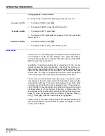
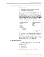
2. Press or to choose the D.O. number to be changed. Place
the D.O. in
MAN
mode by pressing the soft key below
AUT/MAN
until
the display reads
MAN
. Press
to change the state of the digital
output.
3. When changes have been completed, press the soft key below
MAIN MENU
or
PROC DSPL
to return to those environments.
AUXILIARY SWITCH OUTPUTS
This screen is
only
applicable for custom or modified factory configu-
rations. This function provides Boolean outputs from the M/A-SLC
function block during execute mode. These are reset in bypass mode.
The Boolean value (change state) of the four auxiliary switch outputs
on loop station, function code 231, outputs 904 through 907 (one
through four respectively) can be individually adjusted.
These are general purpose switches that are user-defined. The labels
for the switches are assigned during the setup procedures. Most fre-
quent usage is to access digital outputs for alarms, etc.
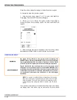
L1: BYP
L2: BYP
DIG CTRL
D.O.
ST
MODE
#1
0
LOCK
#2
0
*LOCK
#3
0
MAN
#4
0
AUT
[SEL - TO CHANGE]
SEL - TO CHANGE
only appears if the current
digital output is in MAN mode. AUT is the default.
MAIN
MENU
PROC
DSPL
AUT/
MAN
s
t
SEL


