INTRODUCTION
PRODUCT OVERVIEW
1 - 4
Physical
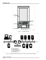
The controller is a panel-mounted, slide-out assembly that conforms
to DIN standards. The assembly contains four printed circuit boards
(main board, operator interface board, power supply board and termi-
nation board) and a faceplate assembly (Fig.
). The operator inter-
face board is attached to the faceplate assembly and is connected to
the main board via a 26-pin ribbon cable connector. Both the power
supply board and the main board plug into card edge connectors on
the termination board. The termination board is assembled to the rear
of the housing and provides plug-in terminal blocks for easy access
when making wiring connections in the field. The terminal blocks are
keyed and marked to prevent possible customer connection errors.
Type SLC22_ controllers have an optional input board for low level or
frequency/pulse inputs. It connects to P6 on the main board. Type
SLC_21 controllers have a serial interface board that allows termina-
tion board access to the serial interface at the rear of the controller.
The serial interface board connects to P7 and P8 on the main board.
The housing is welded sheet steel and contains card guides that are
riveted to the housing for installing the circuit boards. Multiple knock-
outs at the rear of the housing provide two ½-inch and one ¾-inch
conduit entrance facilities for electrical interconnections. The housing
also contains multiple holes in the top and bottom primarily for heat
dissipation.
Figure 1-1. Faceplate with
Main Menu Display
TP80431B
A
/
M
MAIN MENU
L1: MAN
L2: MAN
FULL/SPLIT SCRN
MONITOR
ALARM SUM
BYPASS
TUNE
D.O. CTRL
AUX. SWITCH
SETUP
CONFIGURE
S
E
L


