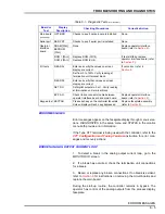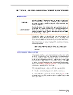
REPAIR AND REPLACEMENT PROCEDURES
REPLACING THE TERMINATION BOARD
8 - 6
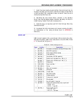
3. Loosen screw and remove the card retainer. Using the handle
(pull tab), remove the main board from the controller housing (Fig.
).
NOTES:
1.
The NVRAM (Fig.
) from the faulty main board can be
removed and installed on the new main board. This eliminates the
need to configure the new board, providing main board failure is not
due to or has not caused NVRAM corruption. If the NVRAM is
replaced, refer to
in Section 3 and enter the
ambient temperature at the wiring terminals.
2.
If necessary to replace ROM U12, refer to Figure
for the
location.
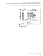
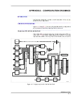
4. To replace the option board, remove it from the main board con-
nector P6. Set all jumpers on the new option board to the same posi-
tions as on the old option board (
). Seat the new option
board in the main board connector P6.
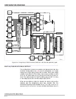
5. To replace the serial interface board, remove it from the main
board connectors P7 and P8. Set all jumpers on the new serial inter-
face board to the same positions as on the old serial interface board
(
). Seat the new serial interface board in the main board
connectors P7 and P8.
6. Assemble by reversing Steps
7. Replacement of the main board requires entering the ambient
temperature at the wiring terminals (refer to
REPLACING THE TERMINATION BOARD
1. Remove power from the controller.
2. Remove the plug-in connectors from the termination board at ter-
minal blocks TB1, TB2, TB3 and TB4.
3. Remove the faceplate assembly and interface board as
described in Steps
through
4. Remove the power supply board and the main board from the
controller housing (refer to
5. Remove the four screws securing the termination board to the
controller housing. Note the S1 switch settings before discarding the
board.
6. Install new termination board in rear of controller housing. Insert
four screws and tighten. Set switch S1 on the new board. If neces-
sary, refer to Table


