CONFIGURATION DRAWINGS
CONFIGURATION DRAWINGS
A - 10
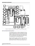
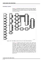
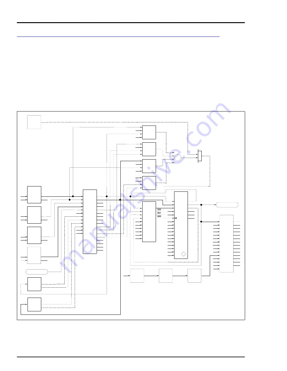
Ratio Controller
This configuration is a two analog input, single analog output, single
PID controller (Fig.
). The control variable is AI1, the wild variable
is AI2 and the analog output is AO1. Both analog inputs have HI/LO
alarm digital outputs associated with them. The PV HI/LO alarms
menu is used to set both alarm limits.
When two temperature inputs are required, the option card must be
installed and the temperature input type selected from the
SETUP-OPTIONS-OPTION BOARD
menu. The control variable is
associated with AI3 and the wild variable is associated with AI4. The
Figure A-10. Ratio Control
(113)
(113)
(113)
ASCII
STDESC
ASCII
STDESC
ASCII
STDESC
1022
1021
1020
S1
S1
S1
TP80458B
ON/OFF
(50)
60
S9
S10
PA
RCJ
mV
ST
(182)
56
57
AI/DEF
CBC
S9
S10
PA
RCJ
mV
ST
(182)
54
55
AI/DEF
CBC
S9
S10
PA
RCJ
mV
ST
(182)
52
53
AI/DEF
CBC
S9
S10
PA
RCJ
mV
ST
(182)
50
51
AI/DEF
CBC
S2
S3
S4
S5
S6
S7
S8
S9
S1
S10
S11
S13
(230)
AI 1
AI 2
AI 3
AI 4
AO 1
AO 2
DI 1
DI 2
DI 3
DO 1
DO 2
DO 3
DO 4
PI
STAT
N/A
N/A
100
101
102
103
104
105
106
107
108
109
110
111
112
113
114
115
116
AI 1
AI 2
AI 3
AI 4
AO 1
AO 2
DO 1
DO 2
DO 3
DO 4
PI 1
SPARE
SLC I/O
CONTROL OUTPUT 1
240
S1
241
H
L
(12)
H//L
250
S1
251
H
L
(12)
H//L
351
350
352
354
353
355
S1
S2
S3
S4
S5
S19
S20
S21
S22
S24
S25
S26
S27
S28
S29
S30
M/A
MFC/P
(80)
C/R
LX
CX
HAA
LAA
HDA
LDA
AO
TRS2
TRPV
PV
SP
SP
O
TR
TS
AX
C/R
C
C-F
T
A
A
S18
S2
S3
S4
S5
S1
(156)
S6
S7
S8
S9
S10
SP
PV
TR
TF
R
FF
N/A
N/A
II
DI
CO
BI
BD
APID
S1
S2
S3
S4
(31)
TSTQ
160
S1
S2
S3
S4
(31)
TSTQ
170
S1
S2
OR
S3
S4
(40)
210
S1
S2
S3
S4
(31)
TSTQ
120
S1
S2
S3
S4
(31)
TSTQ
130
S1
S2
(37)
A
N
D
220
S2
S3
S4
S5
S6
S7
S8
S9
S1
S10
S11
S13
(231)
N/A
N/A
900
901
902
903
904
905
906
907
912
913
ALM
ACK
SL1
SL2
SW1
SW2
SW3
SW4
M/A 1
M/A 2
GPA 1
GPA 2
GPA 3
GPA 4
AUX 1
AUX 2
ALM 1
ALM 2
ASCII
OP 1
OP 2
OP 3
OP 4
S12
S14
S15
908
909
910
911
A/M 1
A/M 2
A/M 3
A/M 4
M/A SLC
CONTROL OUTPUT 1


