INSTALLATION
PRE-OPERATING ADJUSTMENTS
2
-
21
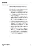
DIGITAL INPUTS
1. Remove power. Switches S1-3 through S1-1 allow selection of iso-
lated or nonisolated inputs for DO1 through DO3. The switches are
factory set for
isolated
inputs.
2. Place the switch in the
off
position to select an
isolated input
.
3. Place the switch in the
on
position to select a
nonisolated input
.
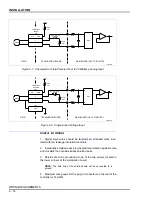
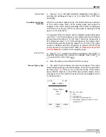
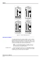
Table
provides a summary of the option settings for the termina-
tion board.
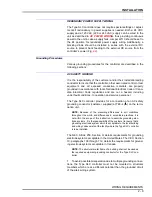
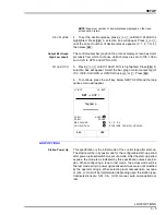
Main Board Jumper Settings
Figure
shows the main board jumper settings that apply when
using the optional input board, the serial interface, or both.
Table 0-1. Termination Board Summary of Options Settings
1
Option
Control
Setting
2
Description
Sample Switch Configuration
Figure No.
Analog input 1
S1-10
On
Current input
through
Off
Voltage input
Analog input 2
S1-9
On
Current input
Off
Voltage input
Analog input 3
S1-8
On
Current input
Off
Voltage input
Analog input 4
S1-7
On
Current input
Off
Voltage input
Analog output 1
S1-6
On
Voltage output
Figures
Off
Current output
Analog output 2
S1-5
On
Voltage output
Off
Current output
(None)
S1-4
None
Not used
—
Digital input 1
S1-3
Off
Isolated input
and
On
Nonisolated input
Digital input 2
S1-2
Off
Isolated input
On
Nonisolated input
Digital input 3
S1-1
Off
Isolated input
On
Nonisolated input
NOTES:
1. Bold text indicates factory settings.
2. Off = open, on = closed.


