CONFIGURATION
FACTORY CONFIGURATION
4 - 10
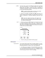
PV Alarm Values
Alarms can be set to occur when the process variable changes above
the PV HI alarm value or below the PV LO alarm value.
NOTE:
Set the alarm values to within the signal’s operating range to
enable the alarm function.
PV HI/LO ALM
1. The alarms screen will appear. If
PV HI ALM
is not highlighted,
press or until it is. Press
. Use or to enter the correct
value for the high alarm. The default value for PV HI ALM is +100,000
and for PV LO ALM is -100,000; the range is -100,000.00 to
+100,000.00 engineering units (EU). Press
. Repeat this step for
PV LO ALM
.
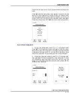
2. Once the alarm values have been set, press the soft key below
NEXT SCRN
to continue. The bad quality screen will appear.
Manual Control Upon Bad Quality of the Analog Inputs/Outputs
A parameter termed
quality
is associated with all I/O points in the
Type SLC controllers. Good quality status is the normal operating val-
ues when all required communications have been established with
the I/O sources and the I/O is within allowed ranges. Bad quality
L1: BYP
CFG:
[SINGLE]
PV ZERO (EU)
XXX.XX
SP ZERO (EU)
XXX.XX
PV SP SPAN
XXX.XX
PREV
SCRN
PROC
DSPL
NEXT
SCRN
1
L1: BYP
CFG:
[SINGLE]
PV HI ALM
XXX.XX
PV LO ALM
XXX.XX
PREV
SCRN
PROC
DSPL
NEXT
SCRN
▲
t
SEL
▲
t
SEL
1


