REPAIR AND REPLACEMENT PROCEDURES
REPLACING THE FACEPLATE/OPERATOR INTERFACE ASSEMBLY
8 - 2
3. Refer to the procedures for removing the operator interface
board.
NOTE:
The main board and the interface board contain semicon-
ductor devices and are subject to damage by static electricity. Refer
to
Reverse these procedures to return output control to the controller.
REPLACING THE FACEPLATE/OPERATOR INTERFACE ASSEMBLY
NOTE:
When replacing any components, verify the firmware revi-
sion level. Make certain that replacement parts match firmware revi-
sion level of components being removed.
Remove power from the controller if the Type CLB01 loop bypass sta-
tion is not in use.
1. Pull down on the small access door below the display area on the
controller faceplate. Loosen the captive locking screw until the face-
plate and operator interface board assembly can be pulled forward.
2. Disconnect the ribbon connector between the main board and the
interface board. Remove the faceplate/operator interface assembly
from the controller housing.
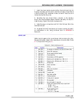
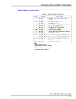
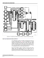
3. If just replacing ROM 1 or ROM 2, refer to Figure
for the loca-
tions.
4. Assemble the new faceplate/operator interface assembly into the
controller housing. While inserting, attach the ribbon cable connector
on the new assembly to the main board.
NOTE:
The contrast of the display has been preset at the factory. If
adjustment is required, refer to
and make the brightness
adjustment.
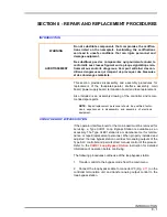
WARNING
Do not disconnect equipment unless power has been switched
off at the source or the area is known to be nonhazardous. Dis-
connecting equipment in a hazardous location with source
power on can produce an ignition capable arc that can injure
personnel and damage equipment.
AVERTISSEMENT
Ne débranchez l'équipement que si l'alimentation a été inter-
rompue ou si l'environnement est non dangereux. Le
débranchement de l'équipement sous tension peut produire
une étincelle, ce qui peut mener à une explosion et à des
blessures au personnel.


