REPAIR AND REPLACEMENT PROCEDURES
REPLACING THE POWER SUPPLY BOARD
8 - 3
REPLACING THE POWER SUPPLY BOARD
1. Remove power from the controller.
2. Loosen the captive screw and remove the faceplate/operator
interface assembly as described in Steps
THE FACEPLATE/OPERATOR INTERFACE ASSEMBLY
3. Loosen screw and remove the card retainer. Use the handle (pull
tab) and remove the main board from the controller housing (Fig.
).
NOTE:
If the controller is to be used with 220/240 VAC supply, or the
controller has to be set for single point grounding, jumpers must be
removed from the power supply board prior to entering into service.
Refer to Figure
and
Section 2. Refer to Figure
for location of jumpers.
4. Slide the power supply board out of the housing. Note jumper set-
tings. Set jumpers on new power supply board and slide the board
into the controller housing. Press board into position making certain
that the card edge is seated in the termination board connector.
5. Assemble the main board and the faceplate/operator interface
assembly into the controller housing. Install card retainer and tighten
screw. While inserting the operator interface assembly, reconnect the
ribbon connector. Tighten the captive locking screw under the door to
secure the faceplate assembly to the controller housing.
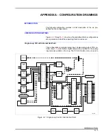
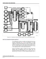
Figure 8-1. Location of ROMs on Operator Interface Board
XU18
ROM 1
XU6
ROM 2
P4
P2
P7
P6
P5
TP80538B


