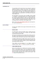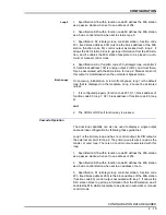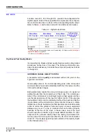
CONFIGURATION
MODIFYING A FACTORY CONFIGURATION
4
-
27
MODIFYING A FACTORY CONFIGURATION
To use a factory configuration as a base configuration and then mod-
ify certain portions of it:
1. Follow the procedures listed under
. Once the configuration is saved, open the access door on the
front of the controller and plug in the Type CTT Configuration and
Tuning Terminal. Enter the module address for the Type SLC control-
ler.
2. Press
CONFIG
and then
F2
on the handheld terminal.
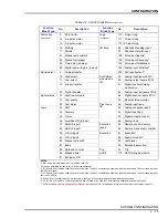
3. Refer to Table
and note the function code number of the func-
tion to modify or delete. To add a function code, refer to the
.
4. Refer to the configuration section of the
instruction. Follow the procedures for adding, mod-
ifying or deleting function blocks.
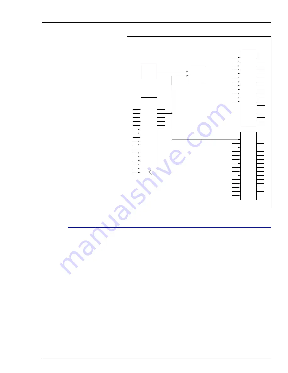
Figure 4-4. Reverse Acting Controllers
(230)
SLC I/O
AI 1
AI 2
AI 3
AI 4
AO 1
AO 2
DO 1
DO 2
DO 3
DO 4
PI 1
SPARE
AI 1
AI 2
AI 3
AI 4
AO 1
AO 2
DI 1
DI 2
DI 3
DO 1
DO 2
DO 3
DO 4
PI
STAT
N/A
N/A
100
101
102
103
104
105
106
107
108
109
110
111
112
113
114
115
116
S1
S2
S3
S4
S5
S6
S7
S8
S9
S10
S11
S13
M/A 1
M/A 2
GPA 1
GPA 2
GPA 3
GPA 4
AUX 1
AUX 2
ALM 1
ALM 2
ASCII
OP 1
OP 2
OP 3
OP 4
ALM
ACK
SL1
SL2
SW1
SW2
SW3
SW4
A/M 1
A/M 2
A/M 3
A/M 4
N/A
N/A
900
901
902
903
904
905
906
907
908
909
910
911
912
913
S1
S2
S3
S4
S5
S6
S7
S8
S9
S10
S11
S12
S13
S14
S15
(231)
M/A SLC
PV
SP
A
TR
TS
MI
AX
C/R
LX
CX
HAA
LAA
HDA
LDA
AO
TRS2
TRPV
SP
O
A
C/R
C
C-F
N+1
N
N+2
N+4
N+3
N+5
S1
S2
S3
S4
S5
S18
S19
S20
S21
S22
S24
S25
S26
S27
S28
S29
S30
M/A
MFC/P
(80)
T
S1
S2
N
(15)
(K)
Σ
7
100.0
S1 = 7
S2 = BLOCK ADDRESS
OF CONTROL
OUTPUT SIGNAL
S3 = 1.00
S4 = -1.00
ANALOG OUTPUT = [ [ 100.0 ]
[ 1.00 ] ]
[ [ CONTROL OUTPUT ]
[ -1.00 ] ]
ANALOG OUTPUT = 100.0 – [ CONTROL OUTPUT ]
×
+
×
TP80444A


