background image

20

…7

ADDRESSABLE PARAMETERS

…7.4   COMMANDER 150/160 – Registers

7.4.3  Totalizer Settings

Register

Variable Label

Read/Write

Limits/Values

75 + 76

Predetermined Value

R

0 to 999999

77 +78

Preset Value

R

0 to 999999

79 + 80

Batch Total

R

0 to 999999

81 + 82

Secure Total

R

0 to 999999

83

Total Go State

W

1 = Go

84

Batch Reset

W

1 = Reset

7.4.4  Maths Functions

Register

Variable Label

Read/Write

Limits/Values

85 + 86

Process Variable Maximum

R

–9999 to 99999

87 + 88

Process Variable Minimum

R

–9999 to 99999

89 + 90

Process Variable Average

R

–9999 to 99999

Summary of Contents for COMMANDER 100

Page 1: ...mentation COMMANDER 100 V100 Controllers COMMANDER 150 160 Indicators Operating Guide MODBUS RTU Communications Option 2674 1 A2 A3 888888 COMMANDER 160 COMMANDER 100 22 61 23 02 C O M M A N D E R 1 0 0 0PEN 411 ...

Page 2: ...to health the following points must be noted 1 The relevant sections of these instructions must be read carefully before proceeding 2 Warning labels on containers and packages must be observed 3 Installation operation maintenance and servicing must only be carried out by suitably trained personnel and in accordance with the information given 4 Normal safety precautions must be taken to avoid the p...

Page 3: ...Status Function Code 01 9 5 2 Read Holding Register Function Code 03 10 5 3 Force Single Coil Function Code 05 11 5 4 Preset Single Register Function Code 06 12 5 5 Loopback Test Function Code 08 13 5 6 Write Multiple Registers Function Code 16 14 6 EXCEPTION RESPONSES 15 6 1 Examples 15 7 ADDRESSABLE PARAMETERS 16 7 1 COMMANDER 100 V100 Coils 16 7 2 COMMANDER 100 V100 Registers 16 7 2 1 Analog In...

Page 4: ...d 2 2 MODBUS serial communications must be configured as either two wire or four wire serial links see Figs 2 1 and 2 2 Two four wire operation must also be selected in the Configuration Mode see Section 3 1 1 INTRODUCTION This Operating Guide describes the COMMANDER 100 150 160 and V100 MODBUS serial data communications option and must be used in conjunction with the standard User Guide part no I...

Page 5: ...Computer Rx Rx Tx Tx A A B B GND 20 21 22 23 24 C100 V100 Tx Rx Tx Rx GND C150 2 ELECTRICAL INSTALLATION Fig 2 1b Two wire Operation Wall Pipe Mounted Instruments 5V 0V 1 8kΩ Pull up Resistor 1 8kΩ Pull down Resistor Host Computer Rx Rx Tx Tx A A B B GND Tx Rx Tx Rx GND 11 12 13 2 2 Two wire and Four wire Connection ...

Page 6: ... 0V A B 1 8kΩ Pull down Resistor 1 8kΩ Pull up Resistor 20 21 22 23 24 Rx Rx Tx C100 V100 Tx C150 GND Host Computer 5V 0V A B 1 8kΩ Pull down Resistor 1 8kΩ Pull up Resistor 0V 5V 0V A B 1 8kΩ Pull down Resistor 1 8kΩ Pull up Resistor Rx Rx Tx Tx GND 9 10 11 12 13 Fig 2 2b Four wire Operation Wall Pipe Mounted Instruments 2 2 Two wire and Four wire Connection ...

Page 7: ...n be connected to a single RS485 adaptor card on a PC The number of slaves can be increased if the driver s serial port permits Connections to the MODBUS serial board must be made as shown in Figs 2 1 to 2 3 Connections on links with multiple slaves must be made in parallel as shown in Fig 2 3 When connecting cable screens ensure that no ground loops are introduced The maximum serial data transmis...

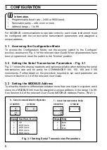
Page 8: ...on Parameters Fig 3 1 Fig 3 1 shows the display readouts and options available when defining the serial transmission rate and bit parity for COMMANDER 100 150 160 and V100 instruments Further detail on the procedure required to set each parameter are shown in Section 4 3 4 of the relevant User Guide 3 3 Setting the MODBUS Address To allow the master to differentiate between more than one slave in ...

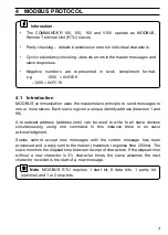
Page 9: ...aves Each slave is given a unique identity address between 1 and 99 A broadcast address address zero can be used to write to all slave devices simultaneously using one command In this instance there is no slave acknowledgment Slaves cannot accept new messages until the current message has been processed and a reply sent to the master maximum response time 250ms The slave monitors the elapsed time ...

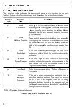
Page 10: ... zeros for points which do not contain defined data and NAKs any request for point numbers greater than 90 Write one discrete Boolean point The slave instrument NAKs this if the point is not currently writeable Write one register This code also applies any existing limits to the register before storage in the instrument The slave instrument NAKs if the register is not currently writeable Echo the ...

Page 11: ...ess must be set to 05 05H Example Read 16 coils from slave 01 starting at coil 6 alarm state 1 Address Function Coil Start Coil Start No of No of Error Check CRC 16 Offset High Offset Low Coils High Coils Low Field 01 01 00 05 00 10 2D C7 5 1 2 Read Coil Status Response The data is packed one bit for each coil 1 ON 0 OFF The response includes the slave address function code quantity of data charac...

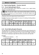
Page 12: ...rror Address Function Start Start of Registers of Registers Check CRC 16 Offset High Offset Low High Coils Low Field 01 03 00 00 00 03 05 CB 5 2 2 Read Holding Register Response The addressed slave responds with its address and function code followed by the information field The information field contains one byte describing the quantity of data bytes to be returned Two bytes are used to return ea...

Page 13: ...oil 30 the coil address 29 1CH is transmitted The use of slave address zero broadcast mode forces all attached slaves to modify the desired coil Example Switch ON coil address 30 auto manual state in slave 01 Coil Coil Data Data Error Address Function Offset Offset Value Value Check CRC 16 High Low High Low Field 01 05 00 1D FF 00 80 FF 5 3 2 Force Single Coil Response The response is confirmation...

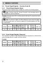
Page 14: ...egister its offset address one less than the register number must be used e g to write to register 25 the offset address 24 18H is transmitted Register Register Data Data Error Address Function Offset Offset Value Value Check CRC 16 High Low High Low Field 01 06 00 18 01 F4 09 DA 5 4 2 Preset Single Register Response The response to a Preset Single Register Response requests is to retransmit the q...

Page 15: ... followed by two bytes to designate the action to be taken Example Data Data Error Address Function Diagnostic Diagnostic Data Data Check CRC 16 Code High Code Low Field 01 08 00 00 A5 37 DA 8D These are considered to be the information fields for the diagnostic mode 5 5 2 Loopback Test Response The Loopback Test Response always echoes the query only diagnostic code 0 bytes 3 and 4 can be used Exa...

Page 16: ...500 to the register address 25 proportional band 1 heat and the value 100 to the register address 26 integral action time in slave 01 Register Register Number of Byte Address Function Start Start Registers Count Offset High Offset Low 01 10 00 18 00 02 04 Holding Holding Holding Holding Error Check Register 24 Register 24 Register 25 Register 25 Field CRC16 High Low High Low 01 F4 00 64 B2 E0 5 6 ...

Page 17: ...The exception response codes sent by the slave are shown in Table 6 1 When a slave detects one of these errors it sends a response message to the master consisting of slave address function code error code and error check fields Exception Response Code Exception Response Name Exception Response Definition Illegal Function Illegal Data Address Illegal Data Value Negative Acknowledgement Memory Pari...

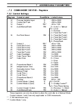
Page 18: ... State R 1 On 19 On Off Output 1 Heat R 1 On 20 On Off Output 2 Cool R 1 On 30 Auto Manual State RW 0 Auto 1 Manual 31 Control Action W 0 Reverse 1 Direct 32 Select Local Set Point W 1 Local 33 Select Remote Set Point W 1 Remote 34 Select Fixed Set Point 1 W 1 Selected 35 Select Fixed Set Point 2 W 1 Selected 36 Select Fixed Set Point 3 W 1 Selected 37 Select Fixed Set Point 4 W 1 Selected 7 2 COM...

Page 19: ...nt 4 RW 999 to 9999 22 Valve Deadband RW 1 to 9999 23 Valve Travel Time RW 1 to 5000 sec 24 Valve Drive RW 0 Close 1 Stop 2 Open 25 Proportional Band 1 RW 1 to 9999 26 Integral Action Time RW 0 to 7200 27 Derivative Action Time RW 0 to 9999 28 Manual Reset RW 0 to 1000 29 Cycle Time 1 RW 9 to 3000 30 Cycle Time 2 RW 9 to 3000 31 Proportional Band 2 RW 1 to 9999 32 Overlap RW 100 to 100 33 Control ...

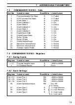
Page 20: ...999 48 Fixed Set Point 4 RW 999 to 9999 7 2 4 Alarm Settings Register Variable Label Read Write Limits Values 51 Alarm Trip 1 RW 999 to 9999 53 Alarm Trip 2 RW 999 to 9999 56 Alarm Hysteresis Value RW 0 to 100 0 None 1 High Process 2 Low Process 57 Alarm Type 1 R 3 Not Valid 58 Alarm Type 2 R 4 Not Valid 5 High Deviation 6 Low Deviation 7 Loop Break 7 2 5 Ramp Soak Settings Register Variable Label...

Page 21: ...te R 1 On 21 Global Maths Reset W 1 Reset 22 Maximum Values Reset W 1 Reset 23 Minimum Values Reset W 1 Reset 24 Average Values Reset W 1 Reset 7 4 COMMANDER 150 160 Registers 7 4 1 Analog Inputs Register Variable Label Read Write Limits Values 1 2 Process Variable Input R 9999 to 99999 3 PV Decimal Places R 0 to 4 7 4 2 Alarm Settings Register Variable Label Read Write Limits Values 50 51 Alarm T...

Page 22: ... 999999 77 78 Preset Value R 0 to 999999 79 80 Batch Total R 0 to 999999 81 82 Secure Total R 0 to 999999 83 Total Go State W 1 Go 84 Batch Reset W 1 Reset 7 4 4 Maths Functions Register Variable Label Read Write Limits Values 85 86 Process Variable Maximum R 9999 to 99999 87 88 Process Variable Minimum R 9999 to 99999 89 90 Process Variable Average R 9999 to 99999 ...

Page 23: ...00 Fax 1 215 674 7183 Italy ABB Kent Taylor SpA Tel 39 0 344 58111 Fax 39 0 344 58278 Client Warranty Prior to installation the equipment referred to in this manual must be stored in a clean dry environment in accordance with the Company s published specification Periodic checks must be made on the equipment s condition In the event of a failure under warranty the following documentation must be p...

Page 24: ...2000 Printed in UK 5 00 IM C100 MOD Issue 4 ABB Automation Inc Instrumentation Division 125 E County Line Road Warminster PA 18974 USA Tel 1 215 674 6000 Fax 1 215 674 7183 ABB Kent Taylor SpA 22016 Lenno Como Italy Tel 39 0 344 58111 Fax 39 0 344 58278 ABB Instrumentation Ltd St Neots Cambs England PE19 3EU Tel 44 0 1480 475321 Fax 44 0 1480 217948 ...

Reviews: