1
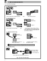
This manual is divided into 5 sections which contain all the information needed to install, configure,
commission and operate the COMMANDER 351. Each section is identified clearly by a symbol as
shown in Fig. 1.
OVERVIEW
Displays and Controls
• Displays and Function Keys
• LED Indication
• Error Messages
Operator Mode (Level 1)
• Single Loop Controller
• Motorized Valve Controller
• Auto/Manual &
Backup Stations
Set Up Mode (Levels 2 to 5)
• Level 2 – Tuning
• Level 3 – Set Points
• Level 4 – Alarm Trip Points
• Level 5 – Valve Setup
8
Configuration Mode (Levels 6 to E)
• Level 6 – Basic Configuration
• Level 7
– Input Configuration
• Level 8
– Alarm Configuration
• Level 9
– Set Point Configuration
• Level A – Control Configuration
• Level B – Operator Configuration
• Level C – Output Configuration
• Level D – Serial Communications
• Level E – System Calibration
Installation
• Siting
• Mounting
• Electrical Connections
Getting
Started
Getting
Started
Table A – Template Applications
B – Output Sources
Table C – Digital Sources
D – Analog Sources
Pull-up Resistors
2 x 100k
Ω
Shunt Resistors
3 x 100
Ω
Panel Clamps
x2
CJ Sensor
x2
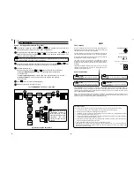
Fig. 1 Overview of Contents
Fig. 2 Foldouts
Fig. 3 Accessories

