Section-5
04-3008_S5_ABB_OPMCPDPA-S2_GB_121202
Page 14/16 ABB
Printed in Switzerland – Modifications reserved
9.
Remove the 4 fixation screws and slide out the UPS-Module (10cm) paying particular attention to the
cable connected to JD7. This operation will disconnect module by the power connection located on
the back of the cabin.
10.
Disconnect cables from connectors JD7.
ATTENTION: BEFORE DRAWING THE UPS-MODULE COMPLETELY OUT, WAIT 5 MINUTES UNTIL
THE INTERNAL DC-CAPACITORS ARE DISCHARGED.
11.
Draw UPS-Module by pulling it out horizontally:
NOTE:
Two persons are needed to pull out the module from the UPS-Frame. The weight of a
DPA 50 S2, 40 kW module is 46.8kg (the weight of DPA 30 S2 , 24kW module is
43.1kg)
12.
Insert new UPS-Module or cover the opening (UPS-Module Compartment) with appropriate
protection cover immediately and fix with four screws.
WARNING
!
MAKE SURE THE INTERNAL DC-CAPACITORS (ELCO) HAVE BEEN
DISCHARGED WAITING AT LEAST 5 MINUTES
WARNING
!
THE LOAD IS NOW DIRECTLY SUPPLIED BY MAINS AND IS NOT
PROTECTED
5.2.3.2
How to Fit Back a Module in a Capacity Multi-Module System
To replace a Faulty Module in a
Capacity Multi-Module System
perform following steps:
1.
Remove UPS-Module compartment protection cover by unscrewing four screws on the front.
2.
Slide two thirds of UPS-Module into dedicated UPS-compartment (make sure not to plug the UPS-
Module into the rear connector).
Connect Control Panel cable to connector JD7.
Push UPS-module to its final position and push strongly to assure good contact on the rear plugs.
NOTE:
Two persons are needed to pull out the module from the UPS-Frame. The weight of a
DPA 50 S2, 40 kW module is 46.8kg (the weight of DPA 30 S2 , 24kW module is 43.1kg).
3.
Tighten the four screws on the front of module;
4.
Check if LED LINE1 and battery are green.
On the LCD: “LOAD OFF, SUPPLY FAILURE” will appear and the LED-indicator will indicate as
shown below:
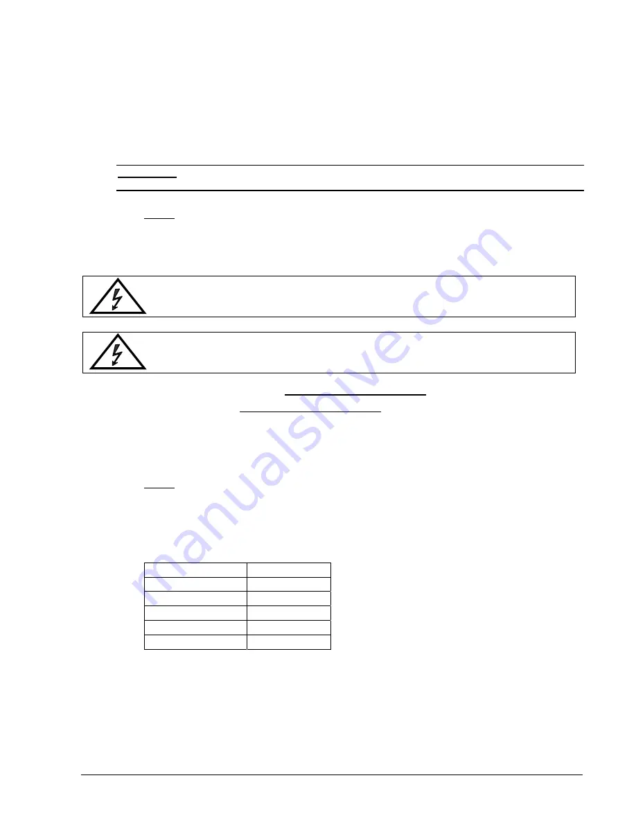
LED Indicator
Colour
LINE 1
Green
LINE 2
OFF
BYPASS OFF
INVERTER OFF
BATTERY Flashing
Green
5.
Close internal and/or external battery fuses/breaker of the new Module
6.
Press both “ON/OFF” Buttons simultaneously to start-up UPS.
LCD panel must display: “LOAD DISCONNECTED PARALLEL SWITCH OPEN” and the LED-
indicator will appear as shown below:


