04-3275_OPM_ABB_CONCEPTPOWER_DPA_500kW_EN_REV-A.docx
Page 39/78 ABB
Modifications reserved
Touching the functional blocks in the mimic diagram, the measurements related to the object selected are displayed.
The interactive blocks are the following:
• Rectifier
• Inverter
• Battery
• Bypass
• Load
The green connecting lines indicate the power flow in the system.
6.4.6
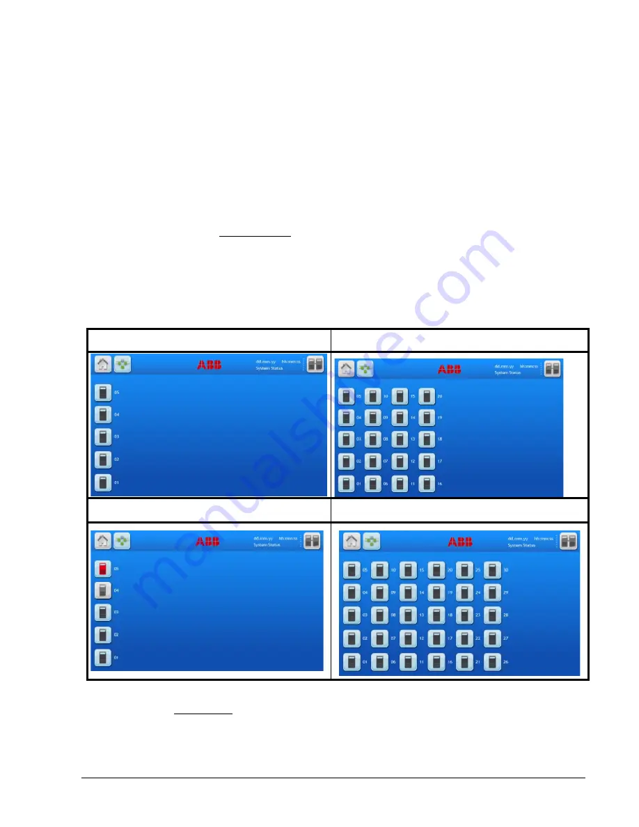
Module selection screen
By pressing the button F (see
6.4.4 Navigation
) directs the user to the module selection screen from where it is
possible to select the module and start the navigation (status and measurements) on module level.
The module selection screen will show the amount of module in the system show the status of each module as
follows:
• Black: module in operation
• White: inactive module / switched off
• Red: module with general alarm
Example with 5 modules all in operation.
Example with 20 modules all in operation.
Example with 5 modules, 01-03 in operation, 04
inactive and 05 with general alarm.
Example with 30 modules all in operation.
By touching on one of the icons the user gets to the mimic diagram and form there the navigation gives the same
possibility but on the module level.


