background image


Contact us 


www.abb.com/ups


ups.sales@ch.abb.com 

© Copyright ABB. All rights reserved. Specification 
subjects to change without notice. 


Summary of Contents for Conceptpower DPA 500

Page 1: ...Conceptpower DPA 500 100 500 kW User Manual 04 3275_OPM_ABB_CONCEPTPOWER_DPA_500kW_EN_REV A docx Copyright 2016 ABB All rights reserved ...

Page 2: ... installed UPS system is grounded to earth and IP 20 rated against electrical shock and foreign objects OPERATIONS INSIDE THE UPS MUST BE PERFORMED BY A SERVICE ENGINEER FROM THE SUPPLIER OR FROM AN AGENT CERTIFIED BY THE SUPPLIER This user manual contains guidelines to check delivery installing and commissioning of the UPS and is intended for people who plan the installation install commission an...

Page 3: ... IMPORTANT NOTE This symbol indicates operator tips particularly useful or important information for the use of the product This symbol and wording does not indicate a dangerous situation PE Protective Earth terminal The PE terminal must be connected to earth prior to making any other connection to the equipment AC alternating current or voltage A terminal to which or from which an alternating cur...

Page 4: ...TRICAL INSTALLATION 15 4 3 WIRING CONFIGURATIONS 16 4 3 1 Single input feed separate batteries configuration 17 4 3 2 Dual input feed common battery configuration 18 4 3 3 AC Wiring instructions 19 4 3 4 DC Wiring instructions 22 4 3 5 Installation Checklist 24 4 4 FRONT VIEW 25 5 CONNECTIVITY 26 5 1 INTERFACING 26 5 1 1 SMART PORT JD1 on each frame Serial RS 232 Sub D9 male 26 5 1 2 Customer inte...

Page 5: ...le Parallel Module System 46 6 5 5 Definition of a Single Multi Cabinet Chain DIP Switch SW1 6 46 6 5 6 Status Screens 46 6 5 7 Main Menu Screen 47 6 5 8 Event Log Screen 47 6 5 9 Measurements Screen 48 6 5 10 Commands Screen 48 6 5 11 UPS Data 49 6 5 12 Set Up User 49 6 5 13 Set Up Service 49 6 6 OPERATING MODES 50 6 6 1 Mode ON LINE INVERTER MODE 50 6 6 2 Mode OFF LINE ECO or BYPASS MODE 50 6 6 ...

Page 6: ...TION 67 10 2 GENERAL CHARACTERISTICS 68 10 3 INPUT CHARACTERISTICS 70 10 4 OUTPUT CHARACTERISTICS 71 10 5 BATTERY CHARACTERISTICS 72 10 5 1 Graph AC AC efficiency with linear load cos phi 1 72 10 6 USER INTERFACE COMMUNICATION 73 10 6 1 System Display 73 10 6 2 DPA Display 74 10 6 3 Mimic Diagram 74 10 7 CUSTOMER INTERFACES 74 10 7 1 Customer inputs dry ports Terminal blocks X3 3 14 74 10 7 2 Outp...

Page 7: ... battery cabinets safely it is recommended to read this manual firstly and then follow the instructions carefully during any operation on the UPS Read carefully all instructions and save this manual for future reference THE MANUFACTURER DOES NOT TAKE ANY RESPONSIBILITY FOR DAMAGES CAUSED THROUGH WRONG MANIPULATIONS OF THE UPS SYSTEM DANGER IT IS PROHIBITED TO REMOVE ANY SCREWS FROM THE UPS SYSTEM ...

Page 8: ...ating the UPS must be in the range 0 C to 40 C The Ideal temperature also recommended to achieve a long life of the UPS and VRLA batteries is 20 C to 25 C The relative humidity should be below 95 non condensing and the max altitude without de rating is 1000m above sea level 2 2 CE MARKING AND DECLARATION OF SAFETY AND EMC CONFORMITY The product has the CE marking in compliance with the following E...

Page 9: ...ptpower DPA 500 TYPE UPS MODEL Dimensions w o packaging in mm Dimensions with std packaging in mm Dimensions w wooden box in mm 5Uxxxx Conceptpower DPA 500 1580x1975x940 1750x2120x1000 1850x2350x1050 TYPE Module Dimensions w o packaging in mm Dimensions with std packaging in mm Dimensions w wooden box in mm A5Mxxxx Active sub module 710x178x750 750x200x800 approx n a P5Mxxxx Passive sub module Tab...

Page 10: ... single freestanding cabinet The cabinets line up and match in style and colour and have safety shields behind the doors for hazardous voltage protection Following configurations are possible of single cabinet configuration Table 4 single cabinet configuration possibilities Nominal power 100kW Nominal power 200kW Nominal power 300kW Nominal power 400kW Nominal power 500kW ...

Page 11: ...t 1 module each each cabinet to be equipped with the parallel kit one parallel cable and one Multidrop cable connect that connect two frames The start up of a multiple cabinet systems is an operation which can be performed by a service engineer form the manufacturer or by a service engineer from an agent certified by the manufacturer Please refer to the service manual to perform this operation pow...

Page 12: ...R INVESTIGATION Figure 3 TiltWatch indicator left when intact and right when tipping has occurred 3 2 STORAGE The packing of the goods protects it from mechanical and environmental damage UPS and Battery cabinets should be store in its original packaging Make sure that the goods are stored indoor protected from water and sunshine in a clean environment IMPORTANT NOTES THE RECOMMENDED TEMPERATURE F...

Page 13: ... THE CENTER OF GRAVITY COG LABEL WHICH MAY NOT BE IN ALWAYS IN THE MIDDLE SEE FIGURE ON THE LEFT DPA 500 EQUIPPED WITH 1 2 MODULES HAVE THE COG IN THE MIDDLE OR CLOSE TO IT WHEREAS A DPA 500 WITH 3 5 MODULES HAS THE SHIFTED TO THE SIDE Perform the following steps to unpack the UPS equipment from the standard packaging 1 and 2 Using a forklift load the unit by paying attention to the COG see the wa...

Page 14: ...is necessary for service and maintenance If the UPS will be installed in bayed enclosures partition walls have to be installed as well Also the needed clearances to allow proper airflow on the UPS system and to allow proper service and maintenance shall be respected as reported in the Tables 5 and 6 here below Table 5 minimum clearances for single UPS installation UPS Model A1 mm B1 mm C D mm DPA ...

Page 15: ...DAMAGE MAY OCCUR TO THE UPS OR THE LOAD EQUIPMENT IF THESE INSTRUCTIONS ARE IGNORED To ensure correct operation of the UPS and its ancillary equipment it is necessary to provide the appropriate wiring and with fuse protection in accordance with the prescribed local standards or with the local regulations law Alternatively refer to the suggested appropriate wiring and fuse protection in the next su...

Page 16: ... AC Top and DC bottom or AC bottom and DC top there is an additional gland plate which can be ordered as option highly recommended One gland plate is included as standard The gland plate is shown in the figure below on the left side the right side shows the indicative positions when having top and bottom cable entry Figure 7 gland plate and its indicative position on the Conceptpower DPA 500 Frame...

Page 17: ... at 230V 758A at 220V Fuse A Type gL or CB quantity x A Cable A quantity x mm2 Fuse D Type gL or CB only needed in parallel system quantity x mm2 Cable D quantity x mm2 500 3 x 1000A 3 pole bolded N 5x 2x240 5x 3x120 4 x 800A 4 pole 5x 2x240 5x 3x120 All connection points are bus bar M12 Recommended tightening torque 42 Nm Table 8 Recommended DC wiring copper wires according to IEC 60950 1 recomme...

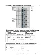
Page 18: ...conditions 725A at 230V 758A at 220V Fuse B Type gL or CB quantity x A Cable B quantity x mm2 Fuse C Type gL or CB quantity x A Cable B quantity x mm2 Fuse D Type gL or CB only needed in parallel system quantity x mm2 Cable D quantity x mm2 500 3 x 1000A 3 pole bolded N 5x 2x240 5x 3x120 3 x 800A 3 pole bolded N 5x 2x240 5x 3x120 4 x 800A 4 pole 5x 2x240 5x 3x120 All connection points are bus bar ...

Page 19: ...on OFF Mains voltage Input Voltage and frequency Input Freq correspond to the values indicated on the type plate of the UPS The type plate Figure 1 is on the inside part of the door in a center position Make sure that the total power of the load is equal or lower than the rated power of the UPS Output power indicated on the type plate of the UPS PE wiring is performed in accordance with the prescr...

Page 20: ...ty only the bottom cable entry is shown here the bars for top entry are positioned the same but mirrored bottom top Bottom cable entry Top cable entry 2 SINGLE INPUT FEED Connect the input wires 3 phases N coming from the LV Distribution Board mains by referring to the table here below Keep the phase rotation in clock wise sense MAINS INPUT CABLE UPS BUSBAR Phase L1 1 L1 Phase L2 1 L2 Phase L3 1 L...

Page 21: ...eally they have to be joined together somewhere upstream the UPS Dual input feed with just 1xN is also possible RECTIFIER INPUT CABLE UPS BUSBAR BYPASS INPUT CABLE UPS BUSBAR Phase L1 1 L1 Phase L1 2 L1 Phase L2 1 L2 Phase L2 2 L2 Phase L3 1 L3 Phase L3 2 L3 NEUTRAL N NEUTRAL N EARTH PE EARTH PE Bottom cable entry Top cable entry 4 Connect the output wires 3 ph N N at the output is not mandatory d...

Page 22: ...d UPS is shut down and voltage free Maintenance Bypass IA1 is open and in position OFF All 5xparallel Isolators IA2 1 IA2 2 IA2 3 IA2 4 IA2 5 are in position OFF open All 5xbattery breakers F3 1 F3 2 F3 3 F3 4 F3 5 are in position OFF open Make sure the battery fuses in the external battery cabinet and on the UPS are open Achieve the DC battery wiring according to the following instructions by mak...

Page 23: ...t s is not important which module you start wiring first Important is to keep clearance for the Filter PCB shown in the figures below Accessing to the filter PCB after the UPS installation is important for the service technicians to measure the voltages safely Battery PE connection bottom cable entry Battery PE connection top cable entry Separate battery bottom cable entry Separate battery Top cab...

Page 24: ...otective covers are installed on the front and back of the cabinet Battery cabinet installation instructions have been completed Air conditioning equipment is installed and operating properly The area around the installed UPS system is clean and dust free It is recommended that the UPS be installed on a level floor suitable for computer or electronic equipment Adequate workspace exists around the ...

Page 25: ...b modules 3 System display 4 Door handles 5 Module dedicated battery breakers F3 1 F3 2 F3 3 F3 4 F3 5 4x125 A 600 800 VDC 6 Module dedicated bypass fuses F2 1 F2 2 F2 3 F2 4 F2 5 3x160 A gG gL NH00 7 Module dedicated output breakers IA2 1 IA2 2 IA2 3 IA2 4 IA2 5 manual switch 8 Slot for SNMP or modem cards 9 Customer interface 10 Parallel interface 11 Spot for the Maintenance Bypass Switch MBS op...

Page 26: ...Interlock Function X1 1 2 Phoenix terminals Multi Cabinet Configuration SW1 6 DIP SWITCH Parallel BUS connector JD8 Sub D25 female 5 1 1 SMART PORT JD1 on each frame Serial RS 232 Sub D9 male The SMART PORT JD1 located on the customer interface board see figure 10 above detail 9 RS 232 serial port that allows the UPS Module to be connected to a computer The connector is a standard D Type 9 pin mal...

Page 27: ...N_BYP External Manual Bypass Ext IA1 N O Min contact load 20mA X3 7 12Vdc X3 6 12V GND 12Vdc 12 VDC source UPS protected Max 200mA X3 5 GND X3 4 GND IN GND REMOTE_ SHUTDOWN RSD Remote Shut down Default setting disabled Possibility to enable and set NO or NC via NewSet X3 3 12Vdc X3 2 C NO REMOTE_ SHUTDOWN RSD Remote Shut down for external switch Max 250Vac 8A 30Vdc 8A 110Vdc 0 3A 220Vdc 0 12A X3 1...

Page 28: ... not both at the same time 5 1 5 JR2 RS232 Interface for Multidrop The Computer Interface JR2 RJ 45 connector located on the distribution part is the Multidrop connection which is needed for multi cabinet configurations To enable the Multidrop communication between cabinets it is necessary to set JP2 jumper correctly on the customer interface board as shown in the table here below Customer Interfa...

Page 29: ...howing the status of the interface board 6 JR3 Graphical display connection 7 SW2 DIP SWITCH for Multidrop configuration 8 JR2 RJ 45 Multidrop connection multi cabinet configuration 9 X3 UPS inputs and 12VDC source X3 5 6 10 X2 UPS outputs dry ports potential free contacts 11 X1 Interlock Function 12 SW1 6 Multi cabinet Configuration switch see 5 1 6 and 6 1 2 4 13 JD8 Parallel BUS connector ONLY ...

Page 30: ...ming upgrading is necessary on site power connection parallel cable Multidrop cable Figure 13 Multi Cabinet Configuration The Multi Cabinet Chain is based on a decentralized bypass architecture i e every UPS is provided with its own static bypass In a parallel system there is always one Master Module and the other Modules are slaves If at any time the master is faulty the next UPS former slave wil...

Page 31: ...ontinuously between each other This is achieved by means of the so called communication BUS Lines After terminating the input and output cabling of each single UPS it is necessary to connect the units together to form the parallel system For this purpose a communication BUS line is connected sequentially between the units Connect communication BUS lines according to Figure 14 NOTE CONNECT THE BUS ...

Page 32: ...e frame ON ON ON OFF ON ON ON See info Only 6 Dip switches are mounted on it and the setting for the parallel configuration must be done according to the above table The Jumper JP1 must be always present inserted on all boards inside the parallel system single or more frames working in parallel The new connector X1 is used only in case the UPS is equipped with the synchronization with main feature...

Page 33: ...n the picture Board NW22085 Jumper Switches configuration Verify that the customer interface board NW22085 of each unit correctly configured according to the following table JUMPER JP 2 on PCB NW22085D with ROM76 12 or NW22085E or later versions First unit OFF Middle Unit ON Last Unit ON Note on the older versions NW22085B C without ROM76 12 make a bridge between X3 11 X3 12 6 2 5 ON OFF Main Butt...

Page 34: ...ons redundant and capacity parallel systems Redundant Parallel Configuration In a redundant parallel system a UPS module may easily be isolated from the parallel system by opening the respective isolator IA2 It is now possible to operate or shut down this unit without influencing the rest of the parallel system The rest of the parallel system will continue to protect the load The isolated UPS Modu...

Page 35: ...hey are disconnected The UPS may be shut down completely if the loads do not need any power supply Therefore the steps in this Paragraph are to be performed only after the load has been disconnected and does not need any power supply To perform a complete shutdown of a Multi Cabinet Configuration proceed as described in the shutdown procedure described in section 6 8 6 4 SYSTEM DISPLAY WARNING ONL...

Page 36: ... the display are detailed in subsequent sections The touchscreen display enables the operator to perform the following Check operational status and measurements Execute operational commands Monitor the power flow through the UPS system Check events and alarm history Silence alarms Adjust programmable parameters Check the status of the batteries 6 4 2 Rear View NOTE PLEASE NOTE THAT THE EMERGENCY S...

Page 37: ...icons and some information are displayed in the top of every screen as indicated in the Figure 17 Figure 18 Display header A Home Directs the user to the navigation screen B Mimic diagram Directs the user to the mimic diagram screen C Warning symbol Warning symbol Appears in case of alarms or events Touching this icon the alarm is silenced and the events screen is displayed D Date Adjustable in th...

Page 38: ...h the UPS system single frame as well as multi cabinet configuration and indicates its status This diagram can be accessed from any screen using the corresponding icon in the display header Figure 19 Mimic Diagram Screen system level The color of each block identify its functional status There are four main colors in the mimic diagram Green In operation White Inactive block Yellow Warning conditio...

Page 39: ...een from where it is possible to select the module and start the navigation status and measurements on module level The module selection screen will show the amount of module in the system show the status of each module as follows Black module in operation White inactive module switched off Red module with general alarm Example with 5 modules all in operation Example with 20 modules all in operati...

Page 40: ...mand is executed the user is immediately re directed to the mimic diagram screen UPS Data Gives information regarding the identity of the UPS User Enables the adjustment of data such as date and time automatic battery test etc Service Enables the service technician to adjust several UPS parameters Figure 20 Home Screen Events Displays a list of recently occurred events with date time event name de...

Page 41: ... operating mode of the UPS Once the command is executed the user is immediately directed to the mimic diagram where the new status of the UPS is indicated Command Load to inverter Load to bypass Battery test Deep battery test Abort battery test Perform alarm test UPS Data This menu gives access to information regarding the manufacturing of the UPS UPS Data Serial Number Manufacturing Firmware Vers...

Page 42: ...L2 Inverter DC L3 Output DC L1 Output DC L2 Output DC L3 I Inverter Offset L1 I Inverter Offset L2 I Inverter Offset L3 I Bypass Offset L1 I Bypass Offset L2 I Bypass Offset L3 I Battery Offset V Battery Offset V Battery Offset Type Power Unit Number Slot ID Cosphi System Parallel Frequency Sync Window Inverter Voltage V Rectifier Voltage V General Alarm Delay Converter Separate Bypass UPS Data Co...

Page 43: ...ad condition the UPS will transfer the load automatically and without interruption to the static bypass mains supply transfer time 0ms 6 4 8 2 Eco mode Offline or bypass mode In Eco mode the load is supplied from the mains through the static bypass Figure 22 Eco mode on Mimic Diagram When the UPS is operating in Eco mode the efficiency of the system is higher 99 In the event of a mains failure the...

Page 44: ... switch closed Load supplied directly from mains Warning indicates in the display Manual bypass is closed OFF Maintenance bypass switch open Normal operating condition Load supplied by inverter Warning indicates in the display Manual bypass is opened NOTE ON MANUAL OR MAINTANENCE BYPASS MODE THE LOAD IS NOT PROTECTED AGAINST ANY MAINS FAILURES OR MAINS DISTURBANCES 6 5 MODULE DISPLAY CONTROL PANEL...

Page 45: ... external alarm condition At the same time an audible alarm will be activated INDICATOR INDICATOR STATUS MEANING ALARM OFF RED No alarm condition Alarm condition LINE 1 GREEN RED Mains rectifier available Mains rectifier not available LINE 2 GREEN RED OFF Mains bypass available Main bypass not ok or not available UPS is turned off BYPASS GREEN OFF Load on bypass Bypass or Eco Mode Bypass not opera...

Page 46: ... the Multi Cabinet Chain Middle in the Multi Cabinet Chain there may be more than one Last in the Multi Cabinet Chain NOTE If a Cabinet is a Single Cabinet then it is seen as the First and Last in an imaginary Chain So the positions of the DIP Switch SW1 6 must be set as shown below Table 12 DIP Switch SW1 6 6 5 6 Status Screens DESCRIPTION LCD DISPLAY 1 Load is protected by UPS power Load is supp...

Page 47: ...n DESCRIPTION LCD DISPLAY 1 Logging Control A log of the last 99 events is stored in the Power Management Display EVENT LOG MEASUREMENTS 2 In Menu Measurements monitor voltages power frequencies currents autonomy etc MEASUREMENTS COMMANDS 3 The Command Menu enables to perform the commands Load to inverter Load to bypass battery test COMMANDS UPS DATA 4 The UPS Data are the UPS personalized informa...

Page 48: ...CURRENT A 00 0 00 0 00 0 11 Active Output Power of all three phases ACTIVE POWER KW 00 0 00 0 00 0 12 Reactive Output Power of all three phases REACTIVE POWER kVAr 00 0 00 0 00 0 13 Apparent Output Power of all three phases APPARENT POWER KVA 00 0 00 0 00 0 14 Output Power of all three phases OUTPUT POWER 00 00 00 15 Battery capacity BATT CAPACITY 00 16 Battery temperature BATTERY TEMPERATURE 00 0...

Page 49: ...mm ss 6 5 12 Set Up User DESCRIPTION LCD DISPLAY 1 Set up Language SET LANGUAGE SET DATE AND TIME 2 Set up Date and Time SET DATE AND TIME SET UP BATT TEST DD MM YY HH MM SS 3 Set up battery test SET BATTERY TEST SET GENERATOR OP DAY OF MONTH 1 31 HOUR OF DAY 1 24 REPETITIVE Y N YES NO 4 Set up operation with Gen Set SET GENERATOR OP NO MORE SETTINGS BATT CHARGE LOCK YES NO BYPASS LOCK YES NO 6 5 ...

Page 50: ...he static bypass Using the control panel the UPS may be easily transferred to Bypass Mode When the UPS is operating in Bypass Mode the efficiency of the system is higher In the event of a mains failure the load will automatically be transferred from mains to inverter within 5 msec this is valid for single and parallel systems The battery charger remains active in the Bypass Mode The Bypass Mode is...

Page 51: ... Green BATTERY Green Green NOTE ON OPERATION MODE MANUAL BYPASS THE LOAD IS NOT PROTECTED AGAINST ANY MAINS FAILURES OR MAINS DISTURBANCES 6 6 4 Output Switch Parallel Isolator IA2 Every UPS unit is provided with an output parallel isolator IA2 which when opened isolates the corresponding unit from the PARALLEL BUS and from the LOAD Once IA2 is open there is no power on the load coming from the UP...

Page 52: ...PA 500 1 Insert fuses for the supply of UPS System in the Input Distribution The LED indicators LINE 1 and battery on UPS Module is lit green On LCD Display LOAD OFF SUPPLY FAILURE will appear 2 UPS Module 1 Press both ON OFF Main Buttons to switch on UPS LCD panel must display LOAD DISCONNECTED PARALLEL SWITCH OPEN and the LED indicator will appear as shown below LED Indicator Colour LINE 1 Green...

Page 53: ...ce Bypass Switch IA1 position ON On LCD MANUAL BYP IS CLOSED will appear and the LED indicator will indicate as shown below LED Indicator Colour LINE 1 Green LINE 2 Green BYPASS Green INVERTER RED BATTERY Green 13 Connect Load to the UPS Output Insert fuses in output Distribution Board Verify on control Panel that the load is on bypass 14 Open Maintenance Bypass Switch IA1 On LCD MANUAL BYP IS OPE...

Page 54: ...an only be executed after the load has completely been de energized NOTE IN THE CASE THAT THE PARALLEL UPS SYSTEM HAS TO BE TURNED OFF THEN BOTH ON OFF BUTTONS ON ALL UPS MODULES HAVE TO BE PUSHED IN THIS CASE THE POWER SUPPLY TO THE LOAD WILL BE INTERRUPTED 1 Verify that the loads are shut down and that there is no need for power supply to the load 2 If the loads are all disconnected press simult...

Page 55: ... and transfer the load to bypass on the control panel of any module On LCD panel LOAD NOT PROTECTED will appear 2 Close Maintenance Bypass Switch IA1 position ON On LCD MANUAL BYP IS CLOSED will appear and the mimic panel will show LED Indicator Colour LINE 1 Green LINE 2 Green BYPASS Green INVERTER RED BATTERY Green 3 Press simultaneously the two ON OFF buttons on the UPS control panel PMD on all...

Page 56: ...PPLY FAILURE will appear and the mimic panel will show LED Indicator Colour LINE 1 Green LINE 2 OFF BYPASS OFF INVERTER OFF BATTERY Flashing Green 3 Close Parallel Isolators IA2 1 IA2 2 IA2 3 IA2 4 IA2 5 depending of the UPS frames and check message PARALLEL SW CLOSED on LCD of each module 4 Press simultaneously the two ON OFF buttons on the UPS control panel PMD on all control panels Unit will st...

Page 57: ...verter then before closing the Maintenance Bypass IA1 transfer load to bypass by means of the command LOAD TO BYPASS in submenu COMMANDS On LCD LOAD NOT PROTECTED will appear 3 Make sure that the system is redundant 4 Press both ON OFF Buttons on the UPS Module simultaneously This will switch the module off NOTE The rest of the system remains on line THE LOAD IS STILL PROTECTED BY DPA 500 5 Open t...

Page 58: ... and the LED indicator will indicate as shown below LED Indicator Colour LINE 1 Green LINE 2 OFF BYPASS OFF INVERTER OFF BATTERY Flashing Green 5 Close internal and external battery fuses breaker if available 6 Press simultaneously both ON OFF Buttons to start up UPS LCD panel must display LOAD DISCONNECTED PARALLEL SWITCH OPEN and the LED indicator will appear as shown below LED Indicator Colour ...

Page 59: ... correct functionality and reliability of the UPS system When the UPS is commissioned the commissioning field service engineer will attach a service record book to the front of the UPS and this will be used to record the full service history of the UPS During a preventative maintenance the field service engineer might carry out some or all of following checks Status and function check of UPS and b...

Page 60: ... the service setup mode 7 4 BATTERY MAINTENANCE DISPOSAL AND RECYCLING The battery maintenance shall be done by a certified Service Partner To ensure an optimum operation of the UPS system and a continuous and efficient protection of the connected load it is recommended to check the batteries every 12 months Batteries contain dangerous substances that will harm the environment if thrown away If yo...

Page 61: ...or missing If site power appears to be OK check the input circuit breakers etc supplying the UPS OUTPUT SHORT There is a short circuit at the output of UPS on load side Check all output connections and repair as required OVERLOAD Load exceeds the UPS rated power Identify which piece of equipment is causing the overload and remove it from the UPS Do not connect laser printers photocopiers electric ...

Page 62: ...EMERCENCY BYPASS WHICH IS AUTOMATICALLY ENABLED IN CASE OF A SINGLE MODULE CONFIGURATION IN THIS CASE THE EPO WILL BE AUTOMATICALLY DISABLED AND MUST BE ACHIEVED IN THE BUILDING FACILITY THE FACIULITY EPO MUST OPEN THE BYPASS PATH The remote shutdown on terminal port X3 3 X3 4 is located on the CONCEPTPOWER DPA 500 frame In order to allow removal maintenance or testing of any remote shut down faci...

Page 63: ...ty power is unreliable at times ensuring that all network systems have constant power can be a difficult task The situation becomes even more complex if systems are managed across a Local Area Network LAN or Wide Area Network WAN around the world When a power failure occurs action can be taken to protect the system and its valuable data If no action is initiated by the operator this event can seri...

Page 64: ... and to any SNMP based management station When UPSServ detects voltage variations or a power failure it can execute various so called system event routines which for example may shutdown the server or send warning to connected users These system event routines which are a part of the UPS Management Software can be adjusted to your demands The UPS management software includes with every serial numb...

Page 65: ...twork management remote monitoring The Simple Network Management Protocol SNMP is a worldwide standardized communication protocol It is used to monitor any device in the network via simple control language The UPS Management Software also provides its data in this SNMP format with its internal software agent The operating system you are using must support the SNMP protocol We offer our software wi...

Page 66: ...te extension slot of the PMC This adapter communicates via the serial port of the UPS and makes a direct multiple server shut down possible without additional SNMP management software Figure 29 Internal SNMP Adapter For detailed information please see Software Manual provided with the PMC Software CD ROM RCCMD Remote Console Command module for a multi server shutdown This stand alone software modu...

Page 67: ...dware and software required for full system operation They share no common components Each UPS module has its own independent static bypass rectifier inverter logic control control panel battery charger and batteries With all the critical components duplicated and distributed between individual units potential single points of failure are eliminated Key Features of CONCEPTPOWER DPA 500 100 kW rate...

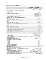
Page 68: ... approx 500kW system with 5 modules 975 kg Acoustic noise acc to IEC 62040 3 in normal mode at 25 C at 100 50 Load 75 67 dBA in battery mode at 25 C at 100 50 Load 73 66 Safety Access operator restricted Degree of protection against hazards and water ingress IP 20 Electromagnetic compatibility compliant Emission UPS Cat Immunity UPS Cat C3 C3 Environmental Storage temperature range 25 70 C Operati...

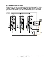
Page 69: ... UPS type on line trasformerfree modular decentralized parallel architecture Parallel capability up to 6 frames Battery not included Performance classification VFI SS 111 Mechanical Dimensions width height depth active sub module passive sub module 710x178x750 mm Mass approx active sub module passive sub module 55 54 kg Additional and usual information Back feed protection included Color Black RAL...

Page 70: ...m s rated with battery charged and input 400 230V 760 152 A maximum with battery charging and input 400 230V 835 167 A total harmonic distortion THDi 3 5 in rush current 100 of rated current Power factor 0 99 100 load Rated short time withstand current ICW 25 for 1 s kA s AC power distribution system TN S TN C TN C S TT note in static bypass mode or eco mode TN C and TN C S can cause PE current to...

Page 71: ...uency steady state rated 50 60 Hz variation in normal mode frq Synchronized with mains 2 4 variation in battery mode free running 0 1 Max synch phase error referred to a 360 cycle 2 Max slew rate 1 Hz s Nominal current In r m s rated 725 145 A overload on inverter 0 5 150 load 5 125 load 20 110 load min fault clearing capability normal mode and battery mode for 100ms 1711 2 36xIn 348 2 4xIn A Load...

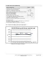
Page 72: ... voltage VRLA NiCd 2 25 1 40 VDC End of discharge voltage VRLA NiCd 1 65 1 05 r m s ripple current percentage of the battery capacity 2 Temperature compensation optional Battery test automatic and periodic battery test selectable 1 IMPORTANT NOTES for small autonomies 20 minutes the UPS supports 40 50 12V blocks the range 42 48 supports any autonomy at output voltage 415 240VAC the minimum 12V blo...

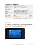
Page 73: ...free contacts For remote signaling and automatic computer shutdown RS485 on RJ45 port Remote monitoring system with remote panel graphical display Optional RS485 on RJ45 port For multidrop purpose Optional Slot for SNMP SNMP card For monitoring and integration in network management Optional 10 6 1 System Display The user friendly touchscreen graphical display on the system level offers the opportu...

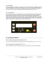
Page 74: ... to bypass and vice versa the corresponding LED indicators will change colour from green normal to red warning The LED s LINE 1 rectifier and LINE 2 bypass indicate the availability of the mains power supply The LED s INVERTER and BYPASS if green indicate which of the two are supplying power to the critical load When the LED indicator BATTERY is lit it means that the battery due to mains failure i...

Page 75: ...when the UPS is are transferred to static bypass mode the lock on the external bypass is released and it possible to switch to position ON The transfer from maintenance bypass back to normal operation happens exactly the other way around The release signal is 230VAC when the maintenance bypass is free and 0V when locked Load Line1 Rectifier Line2 Bypass UPS P01 UPS P02 UPS P03 MBS Auxiliary contac...

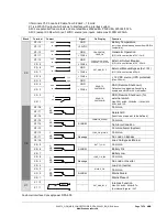
Page 76: ...load 20mA X3 7 12Vdc X3 6 12V GND 12Vdc 12 VDC source UPS protected Max 200mA X3 5 GND X3 4 GND REMOTE_ SHUTDOWN RSD Remote Shut down Default setting disabled Possibility to enable and set NO or NC via NewSet X3 3 12Vdc X3 2 REMOTE_ SHUTDOWN RSD Remote Shut down for external switch Max 250Vac 8A 30Vdc 8A 110Vdc 0 3A 220Vdc 0 12A X3 1 X2 X2 18 Common X2 17 Relais AUX function on request to be defin...

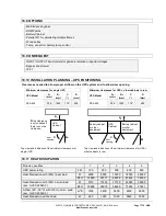
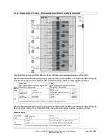
Page 77: ...B2 mm C D mm DPA 500 300 1000 115 400 Top view and indication of the minimum clearances for single UPS Top view and indication of the minimum clearances for UPS other cabinets in row 10 11 HEAT DISSIPATION Module quantities 1 2 3 4 5 UPS power rating kW 100 200 300 400 500 Heat Dissipation with 100 linear load W 4500 9000 13500 18000 22500 BTU 15359 30717 46076 61434 76793 Heat Dissipation with 10...

Page 78: ... at 230V 758A at 220V Fuse A Type gL or CB quantity x A Cable A quantity x mm2 Fuse D Type gL or CB only needed in parallel system quantity x mm2 Cable D quantity x mm2 500 3 x 1000A 3 pole bolded N 5x 2x240 5x 3x120 4 x 800A 4 pole 5x 2x240 5x 3x120 All connection points are bus bar M12 Recommended tightening torque 42 Nm Table 15 Recommended DC wiring copper wires according to IEC 60950 1 recomm...

Page 79: ... conditions 725A at 230V 758A at 220V Fuse B Type gL or CB quantity x A Cable B quantity x mm2 Fuse C Type gL or CB quantity x A Cable B quantity x mm2 Fuse D Type gL or CB only needed in parallel system quantity x mm2 Cable D quantity x mm2 500 3 x 1000A 3 pole bolded N 5x 2x240 5x 3x120 3 x 800A 3 pole bolded N 5x 2x240 5x 3x120 4 x 800A 4 pole 5x 2x240 5x 3x120 All connection points are bus bar...

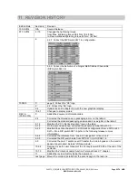
Page 80: ...table 2 Corrected the standard packaging and wooden box weights on the table 3 5 1 2 Modified the X1 Interlock function row on the table 5 1 6 On the second sentence corrected the phoenix terminal X2 with X3 6 2 3 Modified the entire chapter 6 2 3 DIP Switch configuration from a DIP switch SW1 9 to a DIP switch SW1 6 refer to the following release to more information 6 4 6 Corrected the reference ...

Page 81: ...Contact us www abb com ups ups sales ch abb com Copyright ABB All rights reserved Specification subjects to change without notice ...

Reviews: