4
6. Assemblies
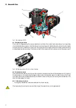
Fig. 1: Basic design of RSD ..
6.1 Standard operation
The motor (1) triggered by the power electronics controls the axially fixed drive sleeve /nut assembly
via oil-lubricated spur gears. A ball bearing screw (see Figure 2) radially fixed by an anti-twist arrester
converts the rotary motion to a linear one. The screw (2) is the upper part of the thrust rod (3) and has
an adjustable mechanical stop. The brake (4) built in the motor acts as a retainer when the power is off.
Fig. 2: Ball bearing screw with nut, sectional drawing
6.2 Handwheel mode
The handwheel (5) allows you to move the actuator manually when the electrical power is off. It acts on
the drive sleeve, via a spiral-toothed gear wheel and a transmission gear. In order to move the thrust
rod, press down the handwheel lock (6) and hold it down while your are turning the handwheel. This
does not disengage the motor.
6.2.1 Direction of action:
-
Turning the handwheel clockwise extends the thrust rod (3).
The handwheel transmission ensures that at least the rated force can be generated!
1
3
2
4
5
6
(not
shown)
7

