background image

14

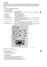
11.1.4Setting

11.1.4.1 “Setting” mode
-

Set electronics to “setting” mode by pressing both push buttons (3) simultaneously for approx. 5
seconds, until both LEDs (2 + 8) are flashing synchronously at approx. 4Hz. („setting mode“ is the
standard electronic unit status after passing the final factory test)

11.1.4.2 Defining first position (0% or 100%) 
(Higher precision in 2nd position)

-

Move to desired position by pressing one of the push buttons (3).

-

To accept the position for 0% or 100%, press push button (10) or (9); the associated LED flashes at
approx. 2 Hz when value is correctly accepted, the other one continues to flash at approx. 4Hz

11.1.4.3 Defining second position (0% or 100%)
-

Move to second position by pressing tho other of the push buttons (3).

-

To accept the position, press push button (10) or (9); both LEDs (2) and (8) are flashing at approx. 2

Hz when values are accepted correctly.

11.1.4.4 Saving the settings
-

Save the settings by simultaneously and shortly pressing the push buttons (10 + 9); the LEDs (2 + 8)
are „ON“ (without flashing) for approx. 5 sec before they extinguish and the setting procedure is
completed.

-

If the selected range is too small for the actuator, both LEDs will flash again at 4Hz. Repeat the ad-
justment procedure with a wider range (min. positioning travel).
(See positioning travel specification on actuator ID label)

11.1.4.5 Correction after setup
-

If the setting is to be corrected after accepting the first value, first press the Reset button (4) and
then repeat the setting.

-

If the correction is to be re-done after saving the settings, the entire adjustment procedure must be
repeated.

11.2Adjustment using the configuration program
Context-sensitive help information is available in the configuration program at all times. For basic han-
dling and installation instructions refer to the associated manual, number 41/68-001.
A conductive ground connection is established between the PC and the CONTRAC electronics with the
RS 232 communication cable. If the PC is grounded, this may cause a ground loop in the installation. 

11.3Functions and signals at the LCP

Table 9: 

Function

Indication

Adjustment

Change-over to adjustment mode:
Press and hold both drive buttons for approx. 5 

seconds

Both LEDs flash synchronously at approx 4Hz 
after time has expired.

Moving to an end position
Use associated drive button on LCP

Both LEDs continue to flash at 4Hz while driv-
ing.

Saving the first end position
Press button 0% or 100%

The associated LED flashes at approx. 2Hz, 
the other continues at 4Hz.

Saving the second end position
Press button 0% or 100%

The associated LED flashes at approx. 2Hz 
synchronously to the first one.

Confirm settings
Press 0% and 100% buttons simultaneously

Both LEDs are briefly „ON“ together and then 
extinguish.

Operation

Normal operation: MAN / AUT

LED off

Driving with button on CSF
Priority over control system

LED off

Bootstrap mode

Electronic is in bootstrap mode during the data trans-
fer of e. g. firmware, objects or motor charcteristics; 
use ECOM688 software for this procedure.

Both LED are „ON“; actuator is not available

Fault (both LEDs flash alternately at 4Hz)

Reset:
Resets fault indications

If no „Failure“ conditions exist, both LEDs 
extinguish (if the actuator had been moved out 
of its operating range, drive it back prior to the 
reset).

Summary of Contents for Contrac RSD 10-10,0

Page 1: ...Instructions 42 68 285 EN Electrical Linear Actuators for Continuous Modulating Control RSD10 RSD200 Contrac Rated Force 10 kN 200 kN ...

Page 2: ...fication 1 1 Actuator ID Label 1 Actuator type 2 Device number No of non standard version 3 Rated force Year of manufacture 4 Permissible ambient temperature 5 Min max positioning travel Min max speed 6 Filled in oil type 7 Associated electronics 8 Not used 9 Not used 10 Available for customer specific information 2 Application Benutzen Sie diese Anweisung immer zusammen mit der Anweisung für die ...

Page 3: ...ure to rain snow etc must be avoided Interior areas of the actuator with risk of condensation are protected by desiccant placed in the follo wing locations Motor under brake cover Position sensor under position sensor cover Electronics delivered separately in terminal enclosure The desiccant guarantees sufficient protection for approximately 150 days It can be regenerated at a temperature of 90 C ...

Page 4: ...or acts as a retainer when the power is off Fig 2 Ball bearing screw with nut sectional drawing 6 2 Handwheel mode The handwheel 5 allows you to move the actuator manually when the electrical power is off It acts on the drive sleeve via a spiral toothed gear wheel and a transmission gear In order to move the thrust rod press down the handwheel lock 6 and hold it down while your are turning the han...

Page 5: ...ng approx 40 50 of Imax RSD 50 3 0 RSD 50 10 0 RSD 100 1 5 RSD 100 10 0 Rated pos force kN 50 100 Stand still force kN aprox 1 2 x rated force break away for a short time in end positions 2 x rated force Positioning speed mm s 0 1 10 0 0 1 10 0 0 1 1 5 0 1 10 0 Servo motor MC 90 BA MC 100 BA MC 90 BA MC 112 BA Weight max stroke 120 mm 150 mm at RSD 100 max stroke 300 mm approx 130 kg approx 155 kg...

Page 6: ...0 BA MC 112 BA Weight max stroke 180 mm max stroke 300 mm approx 400 kg approx 460 kg approx 400 kg approx 460 kg Electronic unit for field installation for rack installation EBN 853 EBS 852 EBN 861 EBS 862 Voltage supply at electronic unit AC 115 V 94 V 130 V or AC 230 V 190 V 260 V 47 5 63 Hz AC 230 V 190 V 260 V 47 5 63 Hz max current AC 115 AC 230 V at electronic unit A 5 0 A 2 5 A 13 5 A Curr...

Page 7: ...appr ltr max stroke 120 mm max stroke 300 mm 7 10 10 12 upon request 7 9 5 oil level mm below inspection screw with fully retracted thrust rod 49 0 150 at 300 mm stroke upon request 95 IMV 1 IMV 3 IMB 5 IMB 5 1 2 1 2 1 2 r00263x2 oil quantity approx ltr max stroke 150 mm max stroke 300 mm 11 15 18 23 upon request 13 19 oil level mm below inspection screw with fully retracted thrust rod 47 15 150 m...

Page 8: ...ible change of oil type Table 8 IMV 1 IMV 3 IMB 5 IMB 5 1 r00262xa 1 2 1 2 1 2 oil quantity approx ltr max Hub 180 mm max Hub 300 mm 15 5 19 5 23 28 5 upon request 18 24 oil level mm below inspection screw with fully retracted thrust rod 48 0 180 mm stroke 30 300 mm stroke upon request 100 Ölsorten ambient temperature factory filling when delivered alternative oil 10 C 65 C ESSO Spartan EP 220 L C...

Page 9: ...ielding 9 3 1 Valve design requirements Consider end position forces of up to 2 5 x the rated force when designing selecting the valve 9 4 Adapting the actuator stroke to the valve stroke In factory the stroke 3 5 mm specified on the actuator ID label is set If it should be necessary to re adjust the stroke observe the minimum and maximum stroke specified in section Technical Data proceed as descr...

Page 10: ...40 N mm2 Use the handhweel to extend the thrust rod link the rod with the valve stem via the clutch Manually retract the thrust rod to check whether or not the external stop of the actuator is on the housing flange before the valve cone gets in touch with the cover If required adjust with the clutch only possible within certain limits Fig 7 Mounting RSD example thrust rod handwheel servomotor hand...

Page 11: ...sure that the supply voltage is available on digital input 1 DI 1 Activate AUT mode via the configuration program 10 1 1 Signal input and output conventional control 10 1 1 1 Standard Fig 9 Write protected when applying 24 V DC to DI 1 24V Uv 30 RB 31 I U 26 27 1 7 2 8 3 9 4 10 13 5 11 14 6 12 15 L N Uv 24V RB 28 29 17 18 19 20 21 22 23 24 17 18 19 20 21 22 23 24 U V W Br Br 1 2 1 2 3 13 14 M 3 H1...

Page 12: ...or detailed information Uv 24V 24V RB RB I U BE 1 BE 2 BE 3 BA 1 BA 2 BA 3 Uv No Y Y 14 28 30 26 13 12 11 9 10 8 7 6 4 3 2 1 5 15 29 31 27 No No Nc Ok Act Val 0 4 20mA Transmitter 4 20mA Option End Pos 0 End Pos 100 controller enable controller L N Bus out Bus in 28 29 30 B B A A 31 S1 17 18 19 20 21 22 23 24 U V W Br H1 Br H2 17 18 19 20 21 22 23 24 1 2 3 13 14 M 3 PE 1 2 r00010x1 Contrac Electro...

Page 13: ...toggle switch Connection of reference potential to the system or protective earth by default set to system of electronic unit 8 LED for 0 position Indication if adjustment procedure saved position or fault by different flash frequencies 9 Accept button 0 Press to define current position as 0 simultaneously press push but ton 9 10 to complete the adjustment procedure 10 Accept button 100 Press to d...

Page 14: ...ettings the entire adjustment procedure must be repeated 11 2Adjustment using the configuration program Context sensitive help information is available in the configuration program at all times For basic han dling and installation instructions refer to the associated manual number 41 68 001 A conductive ground connection is established between the PC and the CONTRAC electronics with the RS 232 com...

Page 15: ...Check the motor pinion gear and the respective mating gear Replace the motor s rotary shaft seal and ball bearings Check the position sensor Change the oil then make a visual check and check for proper operation 12 2 Adjusting the Brake Note that the actuator setting may be changed accidentally by the repelling power of the valve when the brake is released In automatic mode the brake is permanentl...

Page 16: ... gears with the actuator set the first toothed gear in 03 00 o clock position see Figure 15 onto the drive shaft gear 4 slightly move the sensor back and forth to pre tension the toothed gears with the difference z until the second toothed gear snaps in fasten the screws 1 tightly After mounting is completed readjust the actuator range as described in setup section of this manual Figure 14 Positio...

Page 17: ...nect input Brake does not release no audi ble click noise Check the air gap should be around 0 25 mm and the electri cal connection of the brake Check the winding resistance of the brake coil Actuator does not work in auto matic mode although AUT has been selected in the configura tion program Digital input 1 DI 1 has not been connected Connect DI 1 LEDs on the commissioning and service field are ...

Page 18: ... Automation Products GmbH Schillerstr 72 32425 Minden Germany Tel 49 551 905 534 Fax 49 551 905 555 CCC support deapr de abb com ABB has Sales Customer Support expertise in over 100 countries worldwide www abb com instrumentation The Company s policy is one of continuous product improvement and the right is reserved to modify the information contained herein without notice Printed in the Fed Rep o...

Reviews: