background image

24

C O N V A C   V A C U U M   C O N T A C T O R  

I N S T A L L A T I O N   A N D   O P E R A T I O N   I N S T R U C T I O N

6.  Putting into service

6.1 General procedures

All the operations regarding putting into 
service must be carried out by ABB personnel 
or by suitably qualified customer personnel 
with in-depth knowledge of the apparatus 
and of the installation.

Before putting the apparatus into service, carry 
out the following operations

:

check that the voltage and current applied are 

within the specified rated values

check tightness of the power connections of the 

fixed contactors and integrity of the isolating 
contacts of the withdrawable contactors

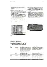
carefully clean the sheets and insulating parts 

with brushes with clean dry cloths

check the earthing connection of the fixed 

contactors

check that no foreign bodies, such as bits of 

packing, have got into the moving parts

check that the contactor vacuum interrupter has 

not been damaged due to accidental impacts

make sure that all the barriers and protective 

shields are correctly installed

carry out the inspections indicated in table 6a

On completion of the operations indicated, check 
that everything is put back in its original position.

The check can only be considered as passed 
if all the tests indicated have had a positive 
outcome. In the case of a negative check, 
do not put the apparatus into service and, 
if necessary, contact ABB Service.

Contactors with self-supplied VTs shall pay special 
attentions to the following items:

Remove the fuse at the VT primary side while 

performing the withstand voltage test of the 
main circuit

Remove the fuse at the VT primary and 

secondary side while performing the withstand 
voltage test of the control circuit

Only the DC resistance test method is allowed 

for primary loop resistance testing


Table 6a

Item inspected

1 Insulation resistance

2 Auxiliary circuits

3 Drive. Open/closed indicator, 

operation counter 

4 Fuse connections, fuse 

protectors

5 truck operation and interlocks

6 VT primary/secondary 

protection fuse

Procedure

Medium voltage circuit With a 2500 V megger, measure 
the insulation resistance between the phases and the 
exposed conductive part of the circuit.
Check that the connections to the control circuits are 
correct: proceed with the relative power supply.
Carry out a few closing and opening operations of the 
contactor.
Check if the screws are fastened, and the snap spring 
and fuse protectors are installed correctly
Execute several racking-in/out  operations
Execute several close/open operations
Check the compliance of operation logic with clause 5.7.3
Check the fuse at primary side

Positive check

The insulation resistance should 

be at least 50 MΩ and remains 

stable.
Operations and signals normal.

Operations and signals normal.

Assembling and protector status 
all correct
Operations and status normal

Operations and status normal

Summary of Contents for ConVac

Page 1: ...ncy and increase your output Optimize investments to reduce your operating costs Safe and reliable protection of your electrical equipment INSTALLATION AND OPERATION INSTRUCTION ConVac Vacuum Contactor 7 2 12 kV 400 A ...

Page 2: ......

Page 3: ...y emission standards IV Safety Information V Operator requirements VI Site Commissioning 1 Overview 2 Delivery inspection and acceptance 3 The loading and unloading 4 Transportation and storage 5 Installation 6 Putting into service 7 Maintenance 8 Spare parts and accessories 9 Product quality and environmental protection Table of contents ...

Page 4: ...mply with the relevant provisions in the manual Attention Pay special attention to the notes marked with this danger sign in the manual Do not exceed the load specified in the technical parameters of the contactor under normal operating conditions The manual should be placed within easy reach of all personnel involved in installation operation and maintenance User s full time personnel shall be re...

Page 5: ...uipment Therefore the following contents may not include instructions on the use of some particular constructions This does not mean decreasing or reducing our professional technical support and quality service commitment to the installation commissioning operation and maintenance of the equipment purchased by users For more information and support please contact Xiamen ABB Switches Co Ltd or visi...

Page 6: ...of the physical characteristics of vacuum insulation According to the requirements of the relevant standards the X ray emitted by the vacuum arc extinguishing chamber shall not exceed the following limits At rated voltage Ur the amount of X ray emission is smaller at a distance of 1 m Not more than 5 μSv At rated short time power frequency withstand voltage Ud distance 1 m X rays The emission rate...

Page 7: ...ble impact of each operation Qualified and authorized to comply with safety Strictly follow the requirements in this manual Verify that safety code standards and installation conditions are met during the installation operation and maintenance phases regulations and local labor standards and to perform the equipment power on power off grounding and check the circuit and other operations Qualified ...

Page 8: ...nal auxiliary power the core may produce magnetic field and electromagnetic force which makes the contactor to close and compresses the opening spring Once the contactor reaches the closing position the system minimizes the power supplied to the closing coil only to keep the contactor in the closing position When the auxiliary power supply is cut off or the voltage of the auxiliary power supply dr...

Page 9: ...requency fr Rated operational current Ie Short time withstand current Ik 4 s Rated peak current Ip Overload withstand current Ik 1 s Overload withstand current Ik 30 s Short circuit breaking capacity Short circuit making capacity Short circuit breaking current Isc combined with fuses Rated short circuit making current Ima combined with fuses category of use Rated duty Mechanical life Opening time ...

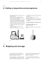
Page 10: ...ng proceed as follows Open the plastic bag Remove the contactor avoiding any kind of mechanical stress to the insulating parts contact arms contact finger and terminals etc Use the special lifting tools for the withdrawable version Check the technical parameter of nameplate and make sure to match order confirmation and shipping notification If product is damaged or does not conform to the order no...

Page 11: ...the transport plate pallet to prevent it moving or overturning Avoid excessive speed sudden starts and stops or sharp changes in direction during contactor handling Only lift the contactor enough to avoid any obstacles on the floor Take care to avoid any impacts with structures other apparatus or with personnel when handling the contactor Never lift a contactor over an area where personnel are pre...

Page 12: ...e GB T 14808 Alternating current high voltage contactor GB T 11022 Common specification for high voltage switchgear and control gear standards 5 3 Normal conditions Follow the recommendations in the GB T 11022 GB T 14808 IEC 62271 1 and 62271 106 standards In more detail Ambient temperature Maximum 40 Average maximum over 24 hours 35 Minimum apparatus for indoor installation 15 Humidity The averag...

Page 13: ... 5 350 5 405 224 296 200 209 194 8 249 183 140 320 231 226 160 54 18 36 22 342 115 115 24 36 47 105 58 54 34 237 9 17 8 36 15 15 6 12 Electrical latched Mechanical latched Only for mechanical latched 4 11 231 256 273 298 15 5 9 5 103 36 6 12 231 142 380 207 5 177 5 140 226 160 320 4 11 36 36 15 15 231 54 18 36 22 342 115 115 24 36 15 5 47 105 115 54 103 17 9 58 8 8 194 350 5 209 237 34 273 Electri...

Page 14: ... contacts horizontal and terminals at bottom E A C B D 5 5 2 Withdrawable version Only for mechanical latched 622 85 22 632 652 205 260 35 155 602 85 63 4 40 5 3 433 4 56 458 150 150 77 4 187 30 118 530 503 99 5 155 101 4 161 C Wall mounted with moving contacts horizontal and terminals at top D Wall mounted with moving contacts horizontal interrupters on the front or rear and vertical terminals E ...

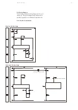
Page 15: ...d wiring diagram is for your reference The actual diagram may differ due to product upgrade or non standard requirements 5 6 1 ConVac Fixed version Electrical latched type Mechanical latched type Mechanical interlock or equal For coil continuity supervision ...

Page 16: ...tched contactor Fig 2 Control circuits of mechanical latched contactor Fig 5 Auxiliary contacts Key symbols Reference number of the diagram figure XDB Connectors for the contactor circuits QAC Contactor SFC Push button or contact for contactor closing SFO Push button or contact for contactor opening KFA Auxiliary control relay or contactor MBC Closing coil AA Power module BGB1 6 Contactor auxiliar...

Page 17: ...40 2 XDB40 1 7 30A 31E 36 SFC KFA SFO KFA 31D 2 AA 3 4 31A 1 31B 31C 2 1 PGC MBC 36 XDB BGF1 SFO 2 31 41 41A XDB 30 13 RLM QAC BGF2 BGF2 3 1 2 4 12 4 47 48 12 12A 48 47 14 XDB1 1 14 1 2 BGF1 O 2 1 7 SFC XDB2 1 XDB1 2 XDB2 2 1 2 XDB1 3 14A 4C 711 712 XDB40 XDB40 XDB3 1 XDB3 3 41 31 30 XDB3 2 13 RiMe 3 4 4B AA 4A 2 1 PGC 2 MBC 43 44 BGT1 XDB71 XDB71 BGT2 43 44 11 12 711A 712A 4 For coil continuity s...

Page 18: ... 4 XDB4 5 XDB4 6 XDB5 7 XDB5 3 7 33 XDB XDB5 1 XDB5 2 28 5 15 BGB2 XDB4 8 7 XDB4 8 18 XDB4 4 3 XDB4 BGB1 XDB4 1 XDB4 2 24 8 7 2 10 9 XDB6 XDB6 2 1 33 6 16 7 17 39 11 21 22 23 29 28 4 3 2 1 2 1 4 3 3 4 2 1 2 1 4 3 5 15 2 1 8 18 3 4 4 3 24 2 10 9 46 4 45 RLE2 XDB15 XDB15 2 1 1 2 XDB QAC 3 XDB 1a 1b 14 4 F301 T1 A B 14A X301 2 1 45 46 4 14 4A 14B XDB11 42 M XDB11 32 2 1 MAT 8 Red Black 32 42 ...

Page 19: ...peration counter BGF1 BGF2 Signaling contact for fuse status RiMe Mechanical latching device BGB1 6 Contactor auxiliary contacts BGT1 Contacts for electrical signaling of contactor in racked in position BGT2 Contacts for electrical signaling of contactor in isolated position BGT3 Contacts for electrical signaling of truck status RLE2 Locking magnet when de energized it mechanically prevents contac...

Page 20: ...he contactor terminals taking care to avoid mechanical stresses produced for example by the conductor busbars on the terminals themselves Interpose a spring and a flat washer between the head of the bolt and the connection The use of bolts according to DIN class 8 8 Standards is recommended also referring to what is indicated in the table Bolt M6 M8 M10 M12 Recommended tightening torque without lu...

Page 21: ...s 300 ms a short impulse signal will make the contactor immediately opens after the closing operation Fixed version XDB1 1 XDB1 3 Withdrawable version XDB 31 XDB 30 opening occurs when the auxiliary power is interrupted either intentionally Fixed version XDB1 1 XDB1 3 Withdrawable version XDB 31 XDB 30 Mechanical latching Closing takes place when the opening coil is Supplied The minimum duration o...

Page 22: ...is as this picture 5 8 3 Withdrawable ConVac with motorized truck Carry out the racking in out test of the motorized truck in the same way as for a manual truck following the instructions below De energize the motor power supply circuit check whether the contactor is in working or testing position whether the positioning interlock on the truck beam is stuck into the corresponding slot on both side...

Page 23: ...mergency opening could be realized in manual mode For fixed contactor please apply 80 N force and 20 mm stroke to pull the mechanical release lever Fig 5e to open the contactor under emergency situations For withdrawable version please use a special tool to apply 100 N force and 35 mm stroke to trigger the emergency opening button on the front cover Fig 5f then open the contactor To perform the op...

Page 24: ... into service and if necessary contact ABB Service Contactors with self supplied VTs shall pay special attentions to the following items Remove the fuse at the VT primary side while performing the withstand voltage test of the main circuit Remove the fuse at the VT primary and secondary side while performing the withstand voltage test of the control circuit Only the DC resistance test method is al...

Page 25: ... circuit should be supplied with another independent power source While performing withstand voltage test guarantee that VT secondary side has been effectively grounded Withstand voltage test between phase A and phase C is forbidden unless when the fuse has been removed Make sure to reinstall the fuses after the test Fig 6b ...

Page 26: ...verse climatic conditions and or in the case of environmental pollution e g heavy contamination or an atmosphere with aggressive agents the frequency of inspections must be increased Visual inspection of the equipment surface for contamination dampness corrosion and discharge Detailed items please refer to table 7a In case of any abnormal conditions it is necessary to be considered for maintenance...

Page 27: ...ctors and insulators surface For dirt that is easy to remove use safe cleaning agent For those not easy to remove use low temperature cleaner After cleaning carefully wipe away the detergent with an alcohol stained cloth and dry it 7 3 3 Checking the degree of vacuum of the interrupter The vacuum interrupter is free of maintenance before reaching the maximum operation cycles After 20 years of stor...

Page 28: ...al conductors Replace the damaged parts which show discoloration melting or damage caused by electric arcs Pay special attention to the moving parts 7 4 Repairs Repairs are necessary if any abnormal signs are sportified during inspection or maintenance Replacement with spare parts and accessories must only be carried out by ABB personnel or by suitably qualified personnel with appropriate training...

Page 29: ... the fuse contact opposite to the one of the striker Tighten the steel band and fully tighten the screw the torque is 10 Nm To dismantle proceed in reverse order Fig 7e Fig 7f Dismantling the fuses Remove the plastic housing Fig 7f for 12 kV contactors unfasten the screws on the plastic housing first Open the locking rings moving them in the direction shown by the arrows using the tool Fig 7g and ...

Page 30: ... plastic housing of the fuse Mount the fuses or the adapter preassembled as indicated in par a with the striker indicated by the arrow facing the opposite side to the one of the contactor tulips and fix them by means of the screws and the spring washers Put back the plastic housing Mounting the fuses Open the locking rings with special tools Fully insert the fuses with the contacts fitted with str...

Page 31: ... with the feeler pin on the opposite side to that of the tulips and fix it with the screws torque is 25 Nm as Fig 7t and 7u Fig 7q Fig 7t Fig 7r Fig 7s Dismantling the fuses To dismantle the fuses and relative adapters proceed in reverse order to the previous chapter of mounting the fuses ...

Page 32: ...es must be turned off Confirm that the contactor is in Open position Remove the front cover of the contactor Remove the fuse by loosing two screws on top of VT Fig 7v remove the fuse cap compress spring and the fuse Fig 7w Reinstall the fuse into the fuse container put back the compress spring and fix the cap onto the VT Reinstall the plastic housing Fig 7u Fig 7v Fig 7w ...

Page 33: ...f the environment laid down according to the ISO 14001 Standard ABB offers its competency and collaboration in facilitating recycling and disposal of the products at the end of their life It is always necessary to act in compliance with the local regulations in force for disposal of the products 8 Spare parts and accessories 9 Product quality and environmental protection List of spare parts Power ...

Page 34: ...ws and tools It s a digital assistant that enables customers to connect to the broadest range of electrification solutions in one place Easy to find what you need by search Get all information about our products applications selection guides installation manuals service certificates and engineering tools etc Saving documents locally updating automatically Receive your expected messages Online cust...

Page 35: ...安装 21 ...

Page 36: ...ications subject to change without notice ABB Xiamen Switchgear Co Ltd No 885 FangShanXiEr Road Xiang an District Xiamen Fujian 361101 Tel 0592 602 6033 Fax 0592 603 0505 ABB China Customer Service Hot Line TEL 800 820 9696 400 820 9696 mail cn ep hotline abb com www abb com ...

Reviews: