41
Electromagnetic Flowmeter
COPA-XE / MAG-XE
9.
Safety Relevant Section of the Instruction Bulletin
9.1
Grounding the Flowmeter Primary
The grounding procedure described is to be observed. In
accordance with DIN VDE 0100, Part 540 a 2.5 mm
2
Cu wire is
to be connected between the ground screw on the flowmeter
primary (on the flange and on the converter housing) to ground.
A ground connection at the converter is essential to meet the
EMC requirements. For technical reasons it also important that
the ground potential be the same as the potential of the
pipeline. An additional ground connection at the connection
terminals is not required.
When a plastic pipeline is used or the pipeline is insulated,
the ground connection is made to a grounding plate or to a
grounding electrode. When the stray voltages exist in the
pipeline it is recommended that a grounding plate be installed
at both ends of the flowmeter primary.
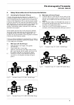
Three grounding possibilities are described below. In cases a)
and b) the fluid is in electrical contact with the pipeline. In case
c) it is isolated form the pipeline.
a)
Metal pipe with fixed flanges
1)
Drill blind holes in the flanges of the pipeline
(18 mm deep)
2)
Thread holes, (M6, 12 mm deep).
3
Attach the ground strap to the flange using a screw
(M6), spring washer and flat washer and connect it to
the ground connection on the flomweter primary.
4)
Connect a 2.5 mm
2
CU wire between the ground
connection on the flowmeter primary and a good
ground.
b)
Metal pipe with loose flanges
1)
In order to assure a trouble free ground connection to the
fluid and to the flowmeter primary in a pipeline with loose
flanges, 6 mm threaded studs should be welded onto the
pipeline.
2)
Attach the ground strap to the threaded stud using a nut,
spring washer and flat washer and connect to the ground
connection on the flowmeter primary.
3)
Connect a 2.5 mm
2
CU wire between the ground
connection on the flowmeter primary and a good ground.
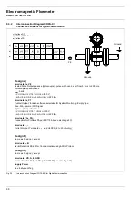
Fig. 22
Flowmeter Primary 1/8”- 4” [DN3 - DN100] Flanged
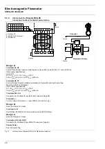
Fig. 23
Flowmeter Primary 1/8”- 4” [DN3 - DN100] Wafer Design
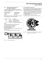
Fig. 24
Flowmeter Primary 1/8”- 4” [DN3 - DN100] Flanged
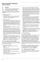
Fig. 25
Flowmeter Primary 1/8”- 4” [DN3 - DN100] Wafer Design
Summary of Contents for COPA-XE
Page 4: ......


