42
Electromagnetic Flowmeter
COPA-XE / MAG-XE
c)
Plastic. Concrete or Pipelines with
Insulating Liners.
1)
Install EMF in pipeline with a grounding plate.
2)
Connect the connection tab on the grounding plate to
the ground connection on the flowmeter primary with a
ground strap.
3)
Connect a 2.5 mm
2
CU wire between the ground
connection on the flowmeter primary and a good
ground.
For plastic pipelines or pipelines with insulating liners the fluid
is grounded by the grounding plate as shown in Figs. 26 & 27
or by grounding electrodes, which are installed in the flowmeter
primary (option). If grounding electrodes are installed the
grounding plates shown in Figs. 26 & 27 are not required.
When there are stray currents in the pipeline it is recommended
that a grounding plate be installed at both ends of the flowmeter
primary.
9.1.1
Grounding Models DE21_ and DE23_
The ground connections are made as shown in Fig. 28. The
fluid is grounded by its contact with the adapter so that an
additional ground connection is not required.
Exception:
Flowmeter primaries with plastic solvent weld process
connections must have a grounding electrode installed in the
flowmeter primary.
9.1.2
Grounding for Flowmeters with Hard or
Soft Rubber Liners
In these flowmeters, sizes 5” [DN 125] and above a conductive
section is integrated in the liner. This section grounds the fluid.
Grounding Plate
Grounding Plate
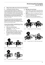
Fig. 26
Flowmeter Primary 1/8”- 4” [DN3 - DN100] Flanged
Grounding Plate
Grounding Plate
Fig. 27
Flowmeter Primary 1/8”- 4” [DN3 - DN100] Wafer Design
Fig. 28
Flowmeter Primary 1/8”- 4” [DN3 - DN100]
Summary of Contents for COPA-XE
Page 4: ......

