background image

INSTRUCTION MANUAL

MAGNETIC FLOWMETERS
10DS3111 Design Level E
Sizes 1 through 12 inches

SERIES 3000 AC MAGNETIC FLOWMETER

PN25011

Summary of Contents for COPA-XM 3000 Series

Page 1: ...INSTRUCTION MANUAL MAGNETIC FLOWMETERS 10DS3111 Design Level E Sizes 1 through 12 inches SERIES 3000 AC MAGNETIC FLOWMETER PN25011 ...

Page 2: ...tem may upset the process being controlled Some process upsets may cause injury or damage NOTICE The information contained in this document is subject to change without notice ABB Inc its affiliates employees and agents and the authors of and contributors to this publication specifically disclaim all liabilities and warranties express and implied including warranties of merchantability and fitness...

Page 3: ... 0 START UP and OPERATION 3 1 3 1 General 3 1 3 2 Dual Frequency Calibration 3 4 4 0 FUNCTIONAL DESCRIPTION 4 1 4 1 Basic Operating Principle 4 1 4 1 1 Signal Voltage Generation 4 1 4 1 2 Volumetric Flow Rate Measurement 4 2 4 2 Operating Characteristics 4 3 4 2 1 Liquid Variables 4 3 4 2 1 1 Liquid Conductivity 4 3 4 2 1 2 Liquid Temperature 4 5 4 2 1 3 Other Liquid Variables 4 5 4 2 2 Metering C...

Page 4: ...10 OUTLINE DIMENSIONS 6 12 INCH FLOWMETER WITH ANSI FLANGES CONTINUOUS SUBMERGENCE 2 13 FIGURE 2 11 OUTLINE DIMENSIONS 1 4 INCH FLOWMETER WITH DIN FLANGES CONTINUOUS SUBMERGENCE 2 14 FIGURE 2 12 OUTLINE DIMENSIONS 6 12 INCH FLOWMETER WITH DIN FLANGES CONTINUOUS SUBMERGENCE 2 15 FIGURE 2 13 BOLT TIGHTENING SEQUENCE 2 16 FIGURE 2 14 GASKET LOCATIONS 2 18 FIGURE 2 15 RECOMMENDED PIPING ARRANGEMENT 2 ...

Page 5: ...ECOMMENDATIONS DIN 2 17 TABLE 4 1 ELECTRODE DIAMETERS 4 4 TABLE 6 1 METER COIL RESISTANCE 6 3 TABLE 7 1 FLANGE GASKETS FOR METER BODY 7 1 TABLE 7 2 PROTECTOR PLATES FOR TEFLON LINED METERS 7 2 TABLE 7 3 LINER PROTECTOR GROUNDING RINGS FOR TEFLON LINED METERS 7 2 TABLE 7 4 GROUNDING RINGS SIZES 1 THROUGH 4 INCHES 7 2 TABLE 7 5 GROUNDING RINGS SIZES 6 THROUGH 12 INCHES 7 3 TABLE 7 6 METER BASE AND J...

Page 6: ...free of any hazardous materials acids alkalis solvents etc A Material Safety Data Sheet MSDS for all process liquids must accompany returned equipment Contact the factory for authorization prior to returning equipment Read these instructions before starting installation save these instructions for future reference Contacting the Factory Should assistance be required with any of the company s produ...

Page 7: ...sponsibility to touch up any damage that has occurred to the finish during shipping or installation of the product Special attention must be given to meter flange bolting pipe mounting of electronics conduit entries and covers that are removed to facilitate installation or repair For continued corrosion protection throughout the product life it is the users responsibility to maintain the product f...

Page 8: ...s such as liquid viscosity and density require no compensation and have no effect on the measurement accuracy of the meter Metering limitations are confined to a minimum threshold of electrical conductivity inherent to the liquid being metered The degree of liquid conductivity has no effect upon metering accuracy as long as it is greater than this minimum level Liquid temperature is limited only t...

Page 9: ...his product is painted with a high performance epoxy paint The corrosion protec tion provided by this finish is only effective if the finish is unbroken It is the users responsibility to touch up any damage that has occurred to the finish during ship ping or installation of the product Special attention must be given to meter flange bolting pipe mounting of electronics conduit entries and covers t...

Page 10: ... Breakdown Refer to the data sheet or data tag on the equipment for the model number of the instrument furnished The details of a specific model number are shown on the following pages 10DS3111E INSTRUCTION MANUAL 1 3 ...

Page 11: ...1 1 2 40 2 50 3 80 4 100 6 150 8 200 10 250 12 300 09 11 12 14 15 17 18 19 20 Flange Standard Pressure Rating DIN PN 10 w Cable Seal Connections DIN PN 16 w Cable Seal Connections DIN PN 25 w Cable Seal Connections DIN PN 40 w Cable Seal Connections ANSI Class 150 w 1 2in NPT Conduit Conn ANSI Class 300 w 1 2in NPT Conduit Conn C D E F P Q Flange Material Carbon Steel 304 Stainless Steel 1 2 Prote...

Page 12: ...ous Location NEMA 4X L Enclosure Classification General Purpose IEC 529 IP 65 NEMA 4X Accidental Submergence IEC 529 IP 67 NEMA 4X 33ft H2O 48h 10m H20 48h Continuous Submergence IEC 529 IP 68 NEMA 4X 33ft H2O 10m H20 Continuous Duty Signal Cable permanently installed Accidental Submergence IEC 529 IP 67 NEMA 4X 33ft H2O 48h 10m H20 48h Tropical Improved Moisture Protection Signal Cable permanentl...

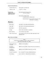
Page 13: ... µS cm System Accuracy Refer to the signal converter instruction bulletin Meter Capacity Specified on meter data tag equal to maximum flow capacity in engineering units Refer to Table 1 4 Environmental Limits Ambient Temperature 13o to 140o F 25o to 60o C Relative Humidity 10 to 90 Non condensing Process Limits TABLE 1 1 LIQUID TEMPERATURE Liner Material Maximum Temperature Minimum Temperature TEF...

Page 14: ...4 SST 224 1 54 219 1 51 218 1 50 212 1 46 205 1 41 DIN PN25 Carbon Steel 362 2 50 362 2 50 362 2 50 362 2 50 362 2 50 304 SST 352 2 43 331 2 28 327 2 25 304 2 10 280 1 93 DIN PN40 Carbon Steel 580 4 00 580 4 00 580 4 00 580 4 00 580 4 00 304 SST 564 3 89 530 3 65 525 3 62 488 3 36 449 3 10 TABLE 1 3 VACUUM LIMIT Meter Size Liner Material Temperature 68o F 20o C 212o F 100o C 266o F 130o C 356o F 1...

Page 15: ...80 0 1500 300 10 250 7925 397 90 0 7925 0 1800 0 2500 550 12 300 10567 528 120 0 10567 2400 3500 800 Each meter is calibrated to determine its flow capacity at a given velocity which has been established as 32 808 ft s 10 m s for the meter capacity Range DN The meter capacity expressed in gpm is recorded on the meter nameplate The meter capacity is the base upon which maximum and minimum limits fo...

Page 16: ...ody 304 SST epoxy finish Flanges carbon steel or 304 SST as specified Meter Housing cast aluminum epoxy finish Electronics Housing cast aluminum epoxy finish 316 SST attachment screws gasketed cover Meter Enclosure Ratings NOTE Enclosures are suitable for indoor or outdoor installation Enclosure ratings apply to the meter Watertight Housing standard NEMA 4X IEC 529 IP65 Accidental Submergence NEMA...

Page 17: ...d with the signal converter for operation and maintenance procedures for the converter The system is normally supplied with a signal converter Interconnection cable and conduit seals are supplied with the signal converter Inspect all items included in the shipment for indications of damage which may have occurred during shipment All damage claims should be reported to the shipping agent involved b...

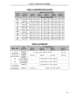
Page 18: ...ary Do not pass a rope or wire sling through the meter the liner will be damaged if the meter is supported by the liner Lift the meter as shown in Figure 2 2 Table 2 1 lists the weights of the meters by size and flange classification Weights shown are approximate and should be used only as a guide when installing the meter TABLE 2 1 METER WEIGHTS Meter Size ANSI Class 150 DIN PN10 16 ANSI Class 30...

Page 19: ...LINER PROTECTOR PLATES SIZES 1 THROUGH 4 INCHES LINER PROTECTOR GROUNDING RINGS SIZES 6 THROUGH 12 INCHES FIGURE 2 1 PROTECTOR PLATES FOR TEFLON LINERS 10DS3111E INSTRUCTION MANUAL 2 3 ...

Page 20: ...FIGURE 2 2 PROPER HOISTING METHOD Figure is for reference only the flowmeter shown in this illustration is not the meter described in this instruction bulletin 10DS3111E INSTRUCTION MANUAL 2 4 ...

Page 21: ...s an optional continuous submergence NEMA 4X IEC 529 IP68 configuration is available It is recommended that the meter not be installed in the immediate vicinity of heavy induction equipment Access for wiring interconnections and servicing of the integrally mounted Signal Converter should be considered when installing the meter A minimum of five inches of overhead clearance is required for cover re...

Page 22: ...FIGURE 2 3 OUTLINE DIMENSIONS 1 4 INCH FLOWMETER WITH ANSI FLANGES Ref 10D4287 10DS3111E INSTRUCTION MANUAL 2 6 ...

Page 23: ...FIGURE 2 4 OUTLINE DIMENSIONS 6 12 INCH FLOWMETER WITH ANSI FLANGES Ref OD 10D 4123 r4 10DS3111E INSTRUCTION MANUAL 2 7 ...

Page 24: ...FIGURE 2 5 OUTLINE DIMENSIONS 6 12 INCH FLOWMETER WITH ANSI FLANGES HI TEMP 10DS3111E INSTRUCTION MANUAL 2 8 ...

Page 25: ...FIGURE 2 6 OUTLINE DIMENSIONS 1 4 INCH FLOWMETER WITH DIN FLANGES Ref 10D4288 10DS3111E INSTRUCTION MANUAL 2 9 ...

Page 26: ...FIGURE 2 7 OUTLINE DIMENSIONS 6 12 INCH FLOWMETER WITH DIN FLANGES 10DS3111E INSTRUCTION MANUAL 2 10 ...

Page 27: ...FIGURE 2 8 OUTLINE DIMENSIONS 6 12 INCH FLOWMETER WITH DIN FLANGES HI TEMP 10DS3111E INSTRUCTION MANUAL 2 11 ...

Page 28: ...FIGURE 2 9 OUTLINE DIMENSIONS 1 4 INCH FLOWMETER WITH ANSI FLANGES CONTINUOUS SUBMERGENCE 10DS3111E INSTRUCTION MANUAL 2 12 ...

Page 29: ...FIGURE 2 10 OUTLINE DIMENSIONS 6 12 INCH FLOWMETER WITH ANSI FLANGES CONTINUOUS SUBMERGENCE 10DS3111E INSTRUCTION MANUAL 2 13 ...

Page 30: ...FIGURE 2 11 OUTLINE DIMENSIONS 1 4 INCH FLOWMETER WITH DIN FLANGES CONTINUOUS SUBMERGENCE 10DS3111E INSTRUCTION MANUAL 2 14 ...

Page 31: ...FIGURE 2 12 OUTLINE DIMENSIONS 6 12 INCH FLOWMETER WITH DIN FLANGES CONTINUOUS SUBMERGENCE 10DS3111E INSTRUCTION MANUAL 2 15 ...

Page 32: ...e center of the meter refer to Figure 2 15 If a control valve is required it is recommended that it be placed downstream of the meter Upstream valves can create turbulence that result in air pockets and may affect the meter s accuracy or cause its output to be noisy A minimum of ten pipe diameters of straight pipe are required upstream between the meter and a control valve or pump 2 4 2 Pipe Conne...

Page 33: ...ial Size in mm Bolt No Size in Max Torque Rate ft lb Bolt No Size in Max Torque Rate ft lb PTFE TEFZEL Rubber 1 25 1 1 2 40 2 50 3 80 4 x 5 8 10 15 25 40 4 x 3 4 8 x 5 8 15 25 15 25 4 100 8 x 5 8 35 40 6 150 8 200 10 250 12 300 8 x 3 4 12 x 7 8 60 75 70 95 12 x 3 4 12 x 7 8 16 x 1 16 x 1 1 8 65 120 150 230 TABLE 2 4 TORQUE RECOMMENDATIONS DIN Liner Material Size in mm Bolt No Size Max Torque Rate ...

Page 34: ...FIGURE 2 14 GASKET LOCATIONS CBI 3007 10DS3111E INSTRUCTION MANUAL 2 18 ...

Page 35: ...FIGURE 2 15 RECOMMENDED PIPING ARRANGEMENT Figure is for reference only the flowmeter shown in this illustration is not the meter described in this instruction bulletin 10DS3111E INSTRUCTION MANUAL 2 19 ...

Page 36: ...the process bonding which is ensuring that the meter body is in contact with the process liquid at both ends of the meter body The bonding procedure places an electrical short circuit across the meter thereby routing any stray current around the liquid in the meter rather than through it From the point of view of grounding there are two basic types of piping systems electrically conductive pipelin...

Page 37: ...s are sized for a 1 4 inch bolt metric M6 fasteners 2 Obtain a bright metal surface around the edges of the tapped hole with a file or emery cloth 3 Attach the bonding wire and another length of ground wire to the flanges as shown Use internal tooth lockwashers as shown in the detail The wire to the good external ground should be 12 AWG or heavier copper wire FIGURE 2 16 GROUNDING PROCEDURE CONDUC...

Page 38: ...14 A gasket is required on both sides of the grounding ring If the meter is supplied with a grounding ring protector plate fastened to the meter flange only one gas ket is required between the grounding ring protector plate and the pipeline flange Proper gasket locations are shown in Figure 2 14 2 Attach the bonding wire and ground wire to the tab of the grounding ring Use internal tooth lockwashe...

Page 39: ...nection box lid since this will break the seal and void the warranty 2 7 Conduit Seal and Pressure Relief In accordance with the National Electrical Code NEC ANSI NFPA 70 Article 501 5 f 3 the flowmeter includes a conduit entry seal and pressure relief to prevent the process liquid from entering the electrical conduit system This safety feature considers the remote possibility of a primary seal fa...

Page 40: ...FIGURE 2 19 CONDUIT ENTRY SEAL INSTALLATION ...

Page 41: ...anged refer to the instruction bulletin supplied with the signal converter The flowmeter does not require zeroing however system zero adjustment must be performed prior to start up The procedure for system zero adjustment is discussed in the signal converter instruction bulletin Start flow through the process piping system that includes the meter Allow a nominal flow through the pipeline for sever...

Page 42: ...ERTER Note The assembly shown is a typical assembly and may not represent the configuration of your specific model Newer models may be different from the configuration shown CUSTOMER CONNECTIONS GROUND TERMINAL JUMPER TO BE IN 16A POSITION 10DS3111E INSTRUCTION MANUAL 3 2 ...

Page 43: ...RY CONNECTIONS FOR REMOTE MOUNTED SIGNAL CONVERTER Note Figure shows electronics without encapsulation material Normally the converter housing is filled with a silicone rubber encapsulant CUSTOMER CONNECTIONS 10DS3111E INSTRUCTION MANUAL 3 3 ...

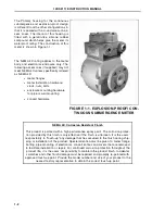
Page 44: ...1 1 Signal Voltage Generation The operating principle of the Series 3000 meter is based upon Faraday s Law of Induction which states that the voltage induced across any conductor as it moves at right angles through a magnetic field will be proportional to the velocity of that conductor This principle finds common application in direct and alternating current generators Essentially the meter consti...

Page 45: ...e rapid the rate of liquid flow the greater the instantaneous value of signal voltage as monitored at the meter electrodes 4 1 2 Volumetric Flow Rate Measurement The meter is a volumetric flow rate measuring instrument This can be shown by substituting the physical equivalent of liquid velocity into equation 1 as follows Equation 2 V Q 4Q A πD2 Substituting for V in equation 1 Es 1 BD 4Q α πD2 and...

Page 46: ...ed by the length of the signal interconnec tion cable as long as the factory supplied or factory approved interconnection cable with driven shields is used The nominal maximum transmission distance is limited to 100 feet 30 m which is the standard length of cable supplied unless specified otherwise The conductivity of a given liquid σ may be determined experimentally under a filled meter condition...

Page 47: ...reshold for specified measurement accuracy for the particular liquid meter size and signal converter combination Liquid conductivities at the operating temperature may also be determined from standard references for many pure liquids Factory Field Engineers are equipped to determine the conductivities of special liquids at the user s site Electrode diameters vary with meter size and type of liner ...

Page 48: ... area of the meter pipe and liquid velocity are required to determine the rate of flow Viscosity and metering pressure are restricted to physical limitations alone such as the pressure limits of the meter pipe flange connections 4 2 2 Metering Characteristics The metering pipe must be completely filled at all times for accurate measurement Where there is a possibility of operation with a partially...

Page 49: ...meter factor resistance network that is connected in series with the magnet coils Changes in magnet drive voltage which cause a variation of flow signal will simultaneously cause a proportional variation of the reference voltage The circuitry will provide an exact ratio and thereby provide immunity to power supply variation The magnet coil drive circuitry is contained in the signal converter 5 2 C...

Page 50: ...al converters being returned to the manufacturer for repair must be free of any hazardous materials acids alkalis solvents etc A Material Safety Data Sheet MSDS for all process liquids must accompany returned equipment Contact the manufacturer for authorization prior to returning equipment NOTE Operation and maintenance procedures for the signal converter are pro vided in the instruction bulletin ...

Page 51: ...efore restoring system power 2 Since signal wiring and operating procedures are dependent upon the type of converter and the mounting option selected the user should refer to the instruction bulletin supplied with the signal converter for system troubleshooting procedures A static performance test for the meter mounted components is discussed in Section 6 3 3 Possible causes of erroneous flow rate...

Page 52: ...s been de energized Turn off the power to the signal converter to de energize the meter Remove cable leads M1 and M2 M3 from the customer terminal block Measure magnet coil series resistance by connecting the ohmmeter between M1 and M2 M3 The value displayed should correspond to that indicated in Table 6 1 A reading of infinity or a short circuit between leads indicates defective coil s If proper ...

Page 53: ...eter housing 2 Place ohmmeter on highest available range for example R x 100 000 3 Connect the ohmmeter minus lead to the meter ground stud and the plus lead to electrode line 1 This reading should be infinite If any resistance can be measured the meter is defective and must be replaced 4 Check the other electrode by connecting the ohmmeter plus lead to line 2 This reading must also be infinite If...

Page 54: ...30 2 50 150 333N415P30 333N415Q10 300 333N416P30 333N416Q10 3 80 150 333N509P30 333N509Q10 300 333N510P30 333N510Q10 4 100 150 333N604P30 333N604Q10 300 333N702P30 333N702Q10 6 150 150 333N811P30 333N811Q10 300 333N801P30 333N801Q10 8 200 150 333N812P30 333N812Q10 300 333N802P30 333N802Q10 10 250 150 333N807P30 333N807Q10 300 333N821P30 333N821Q10 12 300 150 333N806P30 333N806Q10 300 333N803P30 33...

Page 55: ...s and mounting screws Separate grounding rings are not available for this application When ordering specify 614B384U__ and suffix from the table below Protector Plate Material Meter Size Inches mm Flange Rating ANSI Class 150 Flange Rating ANSI Class 300 6 150 8 200 10 250 12 300 6 150 8 200 10 250 12 300 316 sst Suffix 01 07 13 19 04 10 16 22 HAST C Suffix 02 08 14 20 05 11 17 23 TABLE 7 4 GROUND...

Page 56: ...ene gasket 304 SST with TEFLON gasket Inches mm Part Number Part Number Part Number Part Number 6 150 644B009U01 644B009U02 644B009U23 644B009U24 8 200 644B009U03 644B009U04 644B009U25 644B009U26 10 250 644B009U69 644B021U24 644B009U71 644B021U26 12 300 644B009U70 644B021U25 644B009U72 644B021U27 TABLE 7 6 METER BASE AND JUNCTION BOX GASKETS Standard Meter Junction Box Base Gasket D333F021U01 Base...

Page 57: ...e Road Warminster PA 18974 USA Tel 215 674 6000 FAX 215 674 7183 ABB Instrumentation Ltd Howard Road St Neots Cambs England PE19 3EU Tel 44 0 1480 475 321 FAX 44 0 1480 217 948 ABB Instrumentation S p A Via Sempione 243 20016 Pero Milano Italy Tel 39 02 33928 1 Fax 39 02 33928 240 ABB Automation Products GmbH Industriestr 28 D 65760 Eschborn Germany Tel 49 0 6196 800 0 Fax 49 0 6196 800 1849 PN250...

Reviews: