background image

Commissioning Instruction CI/FCB300/FCH300-EN Rev. F 

CoriolisMaster FCB330, FCB350, FCH330, FCH350 

Coriolis Mass Flowmeter 


Measurement made easy 


Summary of Contents for CoriolisMaster FCB330

Page 1: ...Commissioning Instruction CI FCB300 FCH300 EN Rev F CoriolisMaster FCB330 FCB350 FCH330 FCH350 Coriolis Mass Flowmeter Measurement made easy ...

Page 2: ...ing Instruction EN CI FCB300 FCH300 EN Rev F Issue date 05 2014 Translation of the original instruction Manufacturer ABB Automation Products GmbH Process Automation Dransfelder Str 2 37079 Göttingen Germany Tel 49 551 905 0 Fax 49 551 905 777 Customer service center Phone 49 180 5 222 580 Fax 49 621 381 931 29031 Mail automation service de abb com ...

Page 3: ...n in case of measurement of liquids 17 4 6 4 Horizontal installation in case of measurement of gases 17 4 6 5 Difficult installation locations for liquid measurement 18 4 6 6 Difficult installation locations and gas metering 18 4 6 7 Zero balance 18 4 6 8 Installation dependent on the temperature of the medium being measured 19 4 6 9 Installation with option TE1 extended tower length 19 4 6 10 Not...

Page 4: ...for Div 2 Zone 2 40 8 2 1 Version I Active passive current outputs and Version II passive passive current outputs 40 8 3 Electrical data for Div 1 Zone 1 41 8 3 1 Version I Active passive current outputs 41 8 3 2 Version II Passive passive current outputs 41 8 3 3 Special connection conditions 41 8 4 Flowmeter sensor model FCB300 FCH300 42 8 4 1 Temperature class 42 8 4 2 Hazardous area approval c...

Page 5: ... symbols directly on the product must be observed They may not be removed and must be fully legible at all times 1 2 Intended use This device is intended for the following uses To convey liquids and gases including unstable liquids and gases To meter mass flow directly To meter volumetric flow indirectly via mass flow and density To measure the density of the liquid or gas To measure the temperatu...

Page 6: ...tuation Failure to observe this safety information may result in minor or moderate injury The symbol may also be used for property damage warnings NOTICE Property damage This symbol indicates a potentially damaging situation Failure to observe this safety information may result in damage to or destruction of the product and or other system components IMPORTANT NOTE This symbol indicates operator t...

Page 7: ...nst unintended startup During operation with hot media contact with the surface may result in burns Aggressive media may result in corrosion and abrasion of the parts that come into contact with the medium As a result pressurized media may escape prematurely Wear to the flange gasket or process connection gaskets e g aseptic threaded pipe connections Tri Clamp etc may enable a pressurized medium t...

Page 8: ...n important part of our company policy Our products and solutions are intended to have minimum impact on the environment and on people during manufacturing storage transport use and disposal This includes the environmentally friendly use of natural resources We conduct an open dialog with the public through our publications 1 14 Disposal This product is manufactured from materials that can be recy...

Page 9: ... NEMA 4X Approvals and certificates Explosion protection ATEX IECEx Zone 0 1 2 21 22 Zone 0 1 2 21 22 Explosion protection cFMus Class I Div 1 Class I Div 2 Zone 0 1 2 20 21 Class I Div 1 Class I Div 2 Zone 0 1 2 20 21 Explosion protection NEPSI Zone 0 1 2 21 22 Zone 0 1 2 21 22 Hygienic and sterile requirements EHEDG FDA Other approvals On request Enclosure Integral mount design remote mount desi...

Page 10: ...ive Current output 2 4 20 mA passive Pulse output Active not Zone 1 Div 1 or passive External output zero return Yes External totalizer reset Yes Forward reverse flow metering Yes Communication HART protocol Empty pipe detection Yes based on preconfigured density alarm 0 5 kg l Self monitoring and diagnostics Yes Local display totalization Yes Field optimization for flow and density Yes Degree of ...

Page 11: ...e 2 21 22 Zone 1 21 Zone 0 Model number FCT3xx Y0 FCx3xx Y0 FCT3xx A2 FCT3xx Y0 FCx3xx Y0 FCT3xx A2 Remote mount design Transmitter and flowmeter sensor Standard Zone 2 21 22 Zone 1 21 Zone 0 Model number FCT3xx Y0 FCT3xx A2 FCx3xx A1 S1 Remote mount design Transmitter Standard Zone 2 21 22 Flowmeter sensor Zone 1 21 Zone 0 IMPORTANT NOTE Detials can be found in chapter Ex relevant specifications ...

Page 12: ...21 Zone 1 21 Zone 0 20 Model number FCT3xx Y0 FCx3xx Y0 FCT3xx F2 FCT3xx Y0 FCx3xx Y0 FCT3xx F2 Remote mount design Transmitter and flowmeter sensor Standard Class I Div 2 Class I Div 1 Zone 2 21 Zone 1 21 Zone 0 20 Model number FCT3xx Y0 FCT3xx F2 FCx3xx F1 Remote mount design Transmitter Standard Class I Div 2 Zone 2 21 Flowmeter sensor Class I Div 1 Zone 1 21 Zone 0 20 IMPORTANT NOTE Details ca...

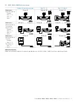
Page 13: ...devices with coplanar counter flanges and use only appropriate gaskets Use only gaskets made from a compatible material for the medium and medium temperature or use only gasket material compatible with hygienic designs Gaskets must not extend into the flow area since possible turbulence could influence the device accuracy The pipeline may not exert any unallowable forces or torques on the device D...

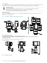
Page 14: ...ot be avoided a sun shade should be installed The limit values for the ambient temperature must be observed Field mount housing The housing is designed for protection class IP 65 67 NEMA 4X EN 60529 and must be mounted using 4 screws For dimensions see Fig 2 and Fig 3 4 3 1 Transmitter in remote mount design option F1 or F2 Fig 2 Dimensions in mm inch 1 Field mount enclosure with window 2 Cable gl...

Page 15: ...s When the housing is open EMC protection is impaired and there is no longer any protection against accidental contact Switch off the power supply before opening the housing To rotate the LCD Display proceed as described below Fig 5 Rotating the LCD display 1 Switch off the power supply 2 Unscrew the housing cover 1 3 Loosen the four fixing screws 2 on the LCD display The LCD display is now hangin...

Page 16: ... tube from draining The devices can be installed directly to or from elbows valves or other equipment unless no cavitation is caused This Flowmeter is designed for industrial installations As long as electromagnetic fields in the environment of the meter are according to best practice as defined in the standards covered in our EC declaration of conformity no additonal efforts have to be taken If e...

Page 17: ...an the cross section of the pipeline in order to prevent the flowmeter sensor from running dry while measurements are being taken Fig 7 Vertical installation in a drop line 1 Supply reservoir 2 Flowmeter sensor 3 Orifice or pipe constriction 4 Valve 5 Product reservoir 4 6 3 Horizontal installation in case of measurement of liquids Fig 8 Horizontal installation liquids 4 6 4 Horizontal installatio...

Page 18: ...a pipeline leads to increased inaccuracies due to the accumulation of fluid or the formation of condensate in the meter tube 4 6 7 Zero balance CoriolisMaster flowmeters do not require in any case a zero point calibration Only under these circumstances a calibration is recommended when measuring below 10 of QmaxDN when very high accuracies are required 0 1 or better the operating conditions pressu...

Page 19: ...in Fig 15 Fig 15 Installation at Tmedium 50 200 58 392 F 1 Insulation 4 6 10 Notes about EHEDG conformity WARNING Risk of poisoning Bacteria and chemical substances can contaminate or pollute pipeline systems and the materials they are made of Observe the following instructions in installations conforming to EHEDG requirements EHEDG certification requires a self draining installation only possible...

Page 20: ...the transmitter The wire cross sectional area of the supply power cable and the circuit breaker used must comply with VDE 0100 and must be dimensioned in accordance with the current consumption of the flowmeter measuring system The leads must comply with IEC 227 and or IEC 245 The circuit breaker should be located near the transmitter and marked as being associated with the device The power supply...

Page 21: ...screw the cover for the connection area 2 Prepare the cable ends and feed them into the connection area through the cable entry points 3 Remove the terminal cover and connect the power supply cables as shown in the connection diagrams 4 Replace the terminal cover 5 Connect the signal input and output cables as shown in the connection diagrams Connect the cable shielding if used to the designated g...

Page 22: ...T NOTE Use suitable wire end sleeves when connecting the cables Fig 18 Signal cable assembly dimensions in mm inch 1 Wire mesh shield 2 Foil shield continuity wires twisted 3 Foil shield 4 Grounding clamp 5 Continuity wire 6 Wire end sleeves 1 Strip the signal cable as shown 2 Cut the wire mesh shield to a length of approx 15 mm 0 59 inch 3 Remove the cable core and foil shield from the wire pairs...

Page 23: ...c 1 1200 Hz Logic 0 2200 Hz Maximum signal amplitude 1 2 mAss Load at current output 250 560 Ω in hazardous area maximum 300 Ω Cable Design Two wire cable AWG 24 twisted Maximum length 1500 m 4921 ft See the interface description for detailed information System integration Communication configuration parameterization can be performed with the DTM Device Type Manager available for the device and th...

Page 24: ...4 V AC 50 60 Hz 24 V DC 31 32 Current output 1 active 0 4 20 mA 0 Ω RB 560 Ω FCT300 A1 F1 1 0 Ω RB 300 Ω Current output 1 passive 4 20 mA 0 Ω RB 600 Ω source voltage 12 Uq 30 V 33 34 Current output 2 passive 4 20 mA 0 Ω RB 600 Ω source voltage 12 Uq 30 V 51 52 Pulse output passive fmax 5 kHz pulse width 0 1 2000 ms 0 001 1000 pulses unit Closed 0 V UCEL 2 V 2 mA ICEL 220 mA Open 16 V UCEH 30 V DC ...

Page 25: ...t outputs A Active B Passive I Internal E External Digital switching output and digital switching input Fig 22 A Output for system monitoring min max alarm for empty meter tube or forward reverse signal B Input for external totalizer reset or external output zero return I Internal E External Pulse output Fig 23 Active passive pulse output A Active B Passive optocoupler I Internal E External ...

Page 26: ...en Sensor 2 93 Not used 88 Yellow Sensor 2 94 Not used 89 Black Temperature 95 Blue Temperature 90 Violet Temperature 96 Red Temperature IMPORTANT NOTE The precise position of the PA terminals may vary according to the device type Each terminal is marked accordingly When the FCT330 FCT350 transmitter is connected to the FCB330 FCB350 FCH330 FCH350 flowmeter sensor the transmitter must also be conn...

Page 27: ...color Function 85 White Sensor 1 91 Gray Driver 86 Brown Sensor 1 92 Pink Driver 87 Green Sensor 2 93 Not used 88 Yellow Sensor 2 94 Not used 89 Black Temperature 95 Blue Temperature 90 Violet Temperature 96 Red Temperature IMPORTANT NOTE The wires must be connected in pairs in order to ensure EMC protection The following flowmeter sensor transmitter combinations are permitted FCB330 FCH330 flowme...

Page 28: ...e position of the fuses and the fuse values are listed in the spare parts list in the operating instructions for the device 6 3 Basic Setup IMPORTANT NOTE For additional information regarding operation of the LCD display refer to the Configuration parameterization operation section For detailed descriptions of all menus and parameters refer to the operating instructions for the device The device c...

Page 29: ...t in case of Zone 1 or Div 1 approved meters this jumper will be in position B active although the pulse output is passive 6 5 Operating protection switch Fig 27 Operating protection switch In addition to password protection it is possible to activate hardware write protection Turning the switch 1 clockwise activates the programming protection while turning the switch anti clockwise deactivates it...

Page 30: ...afe circuits It is not permitted to combine intrinsically safe and non intrinsically safe circuits On intrinsically safe circuits equipotential bonding must be in place along the entire length of the cable used for the current outputs The rated voltage of the non intrinsically safe circuits is Um 60 V IMPORTANT NOTE The cable glands are supplied in black by default If the signal outputs are wired ...

Page 31: ...otection class restricted breathing nR WARNING Potentially adverse effect on protection class The operator must check the device in accordance with IEC 60079 15 following installation or maintenance or each time the housing has been opened see chapter Important notes to test the device Important notes to test the device According to IEC 60079 15 chapter 23 2 3 2 1 2 Equipment without test port obs...

Page 32: ...sunlight cannot be avoided a sun shade should be installed The limit values for the ambient temperature must be observed Change from two to one column 6 6 7 Changing the type of protection When installed in DIV 1 Zone 1 the FCB330 350 FCH330 350 and FCT330 350 models can be operated at Signal Data INPUT OUTPUT with different types of protection Signal Data INPUT OUTPUT as intrinsically safe ia ib ...

Page 33: ...t in length It is essential that the temperature classes as per the approvals contained in the section titled Ex relevant specifications acc to cFMus are observed Please observe the drawing 3KXF002126G0009 in the appendix 6 7 2 Cable entries Special instructions for devices with North American certification Devices certified in accordance for North America are only ever supplied with 1 2 NPT threa...

Page 34: ... non intrinsically safe circuit in Div 2 operated as a non incendive device NI If a device which is already installed is required to provide a different type of protection the following measures must be implemented inspections must be performed in accordance with applicable standards 1 Type of protection 2 Type of protection Required step check Housing XP Umax 60 V Outputs non IS Housing XP Output...

Page 35: ...uts Model FCx3xx A1 FCT3xx A1 or FCx3xx A2 FCT3xx A2 or FCx3xx S2 FCT3xx S2 Type of protection nA Zone 2 General operating values Type of protection e Zone 1 Type of protection ib Zone 1 Current output 1 active Terminals 31 32 Terminal 32 is connected to PA Ui V Ii mA Ub V Ib mA U V I mA Uo V Io mA Po mW Co nF Co pa nF Lo mH 20 100 500 217 0 3 8 30 30 30 30 60 35 Ui V Ii mA Pi mW Ci nF Ci pa nF Li...

Page 36: ...onnection conditions The output circuits are designed so that they can be connected to both intrinsically safe and non intrinsically safe circuits It is not permitted to combine intrinsically safe and non intrinsically safe circuits In case of a change of type of protection observe chapter 6 6 7 On intrinsically safe circuits equipotential bonding must be in place along the entire length of the ca...

Page 37: ... F T5 85 C 185 F 85 C 185 F 75 C 167 F T6 65 C 149 F 65 C 149 F 60 C 140 F Model FCx3xx A2Y or FCx3xx S2Y Zone 2 Ambient temperature 40 C 104 F 50 C 122 F 60 C 140 F Temperature class T1 200 C 392 F 200 C 392 F 180 C 356 F T2 200 C 392 F 200 C 392 F 180 C 356 F T3 180 C 356 F 180 C 356 F 180 C 356 F T4 115 C 239 F 115 C 239 F 115 C 239 F T5 80 C 176 F 80 C 176 F 75 C 167 F T6 60 C 140 F 60 C 140 F...

Page 38: ...FCx3xx A2Y or FCx3xx S2Y integral mount design in Zone 2 Approval Marking Comment ATEX II 3 G Ex nA nR IIC T6 T2 II 2 D Ex tD IIIC T85 C Tmedium IECEx or NEPSI Ex nA nR IIC T6 T2 Gc Ex tb IIIC T85 C Tmedium Db Modell FCx3xx A1Y or FCx3xx S1Y integral mount design in Zone 1 Approval Marking Comment ATEX Version II II 1 2 G Ex d e ia IIC T6 T2 II 2 D Ex ia tb IIIC T85 C Tmedium 2 passive analog outp...

Page 39: ...in Zone 2 Sensor in Zone 0 1 or 2 Approval Marking Comment ATEX II 3 2 G Ex nA nR ia IIC T6 II 2 D Ex tb ia IIIC T85 C IECEx or NEPSI Ex nA nR ia IIC T6 Gc Gb Ex tb ia IIIC T85 C Db Modell FCT3xx A1 or FCT3xx S1 Transmitter in Zone 1 Sensor in Zone 0 1 or 2 Approval Marking Comment ATEX Version II II 2 1 G Ex d e ia IIC T6 II 2 1 D Ex ia tb IIIC T85 C 2 passive analog outputs outputs ia e dependin...

Page 40: ...input and output Passive Version II Output option A3 H3 in the order number Current output 1 Passive Current output 2 Passive Pulse output Passive Switching input and output Passive 8 2 Electrical data for Div 2 Zone 2 8 2 1 Version I Active passive current outputs and Version II passive passive current outputs Model FCx3xx F2 FCT3xx F2 Type of protection NI Vmaxo V Imaxo mA Current output 1 Termi...

Page 41: ...4 30 30 60 300 2000 0 47 0 47 0 17 Pulse output active or passive Terminals 51 52 30 65 60 300 2000 0 47 0 47 0 17 Switching output passive Terminals 41 42 30 65 60 300 2000 0 47 0 47 0 17 Switching input passive Terminals 81 82 30 10 60 300 2000 0 47 0 47 0 17 All inputs and outputs are electrically isolated from one other and from the power supply Change from one to two columns 8 3 3 Special con...

Page 42: ... 2 Ambient temperature 40 C 104 F 50 C 122 F 60 C 140 F Temperature class T1 200 C 392 F 200 C 392 F 180 C 356 F T2 200 C 392 F 200 C 392 F 180 C 356 F T3 180 C 356 F 180 C 356 F 180 C 356 F T4 115 C 239 F 115 C 239 F 115 C 239 F T5 80 C 176 F 80 C 176 F 75 C 167 F T6 60 C 140 F 60 C 140 F 60 C 140 F Ambient and process conditions Tamb 20 60 C 4 140 F Tamb optional 40 60 C 40 140 F only for integr...

Page 43: ...Ex nA IIC T6 T2 ZN 21 AEx tb IIIC T85 C T165 C FM marking Canada NI CL I II III Div 2 GPS ABCDEFG Ex nA IIC T6 T2 Model FCx3xx F2Y integral mount design in Zone 2 Div 2 Approval Marking Comment FM marking US NI CL I II III Div 2 GPS ABCDEFG DIP CL II Div 1 GPS EFG DIP CL III Div 1 2 CL I ZN 2 AEx nA nR IIC T6 T2 ZN 21 AEx tb IIIC T85 C T165 C FM marking Canada NI CL I II III Div 2 GPS ABCDEFG DIP ...

Page 44: ...v 1 GPS ABCD DIP CL II Div 1 GPS EFG DIP CL III Div 1 2 CL I ZN 1 AEx d ia ib IIC T6 or CL I ZN 1 AEx d ia IIC T6 ZN 21 AEx ib ia tb IIIC T85 C or ZN21 AEx tb ia IIC T6 Active passive analog outputs outputs ib e depending on user wiring FM marking Canada Version II IS CL I Div 1 GPS ABCD NI CL I II III Div 2 GPS ABCDEFG XP CL I Div 1 GPS BCD DIP CL II Div 1 GPS EFG DIP CL III Div 1 2 Ex d ia IIC T...

Page 45: ...e found at the name plate of the meter Model FCT3xx Y0 Transmitter in General Purpose and Sensor in Zone 2 Div 2 or Zone 0 Div 1 Approval Marking Comment FM marking US NI CL I II III Div 2 GPS ABCDEFG DIP CL II Div 1 GPS EFG DIP CL III Div 1 2 FM marking Canada NI CL I II III Div 2 GPS ABCDEFG DIP CL II Div 1 GPS EFG DIP CL III Div 1 2 Model FCT3xx F2 Transmitter and Sensor in Zone 2 Div 2 Approva...

Page 46: ... XP CL I Div 1 GPS ABCD DIP CL II Div 1 GPS EFG DIP CL III Div 1 2 CL I ZN 1 AEx d ib ia IIC T6 or CL I ZN1 AEx d ia IIC T6 ZN21 AEx ib tb ia IIIC T85 C or ZN21 AEx tb ia IIC T6 Active passive analog outputs outputs ib e depending on user wiring FM marking Canada Version II IS CL I Div 1 GPS ABCD NI CL I II III Div 2 GPS ABCDEFG XP CL I Div 1 GPS BCD DIP CL II Div 1 GPS EFG DIP CL III Div 1 2 Ex d...

Page 47: ...ntered are checked for plausibility if they are not plausible a corresponding message appears on the LCD display Magnet stick operation The magnet stick provides an alternative means of configuring the device even when the housing cover is closed To execute the functions hold the active side of the magnet stick against the corresponding areas on the LCD display These areas are identified by the sy...

Page 48: ...tion The device parameters can be displayed and changed on the configuration level IMPORTANT NOTE If the message Error operating protection appears on the LCD display hardware write protection has been activated with the operating protection switch V 98 14 V 12 000 m3 1 Use to switch to the configuration level A menu option now appears at random on the LCD display 2 Use or to select the Prog level...

Page 49: ...e is selected from a list of parameter values Submenu Unit 1 Select the parameters you want to set in the menu 2 Use ENTER function to call up the parameter for editing 3 Use oder to select the required value 4 Use ENTER function to confirm your selection Numerical entry When a numerical entry is made a value is set by entering the individual decimal positions QmMax 180 00 kg h 1 Select the parame...

Page 50: ...ce Prog level Blocked Standard Specialist Service Language Mode of operation Flow indication Directional display Signal Level DensiMass Code DensiMass Min Density Concentration Medium Variable Matrix Configuration Number matrices Number temp Number conc Enter conc in Reset matrix Label Unit name Min concentr Max concentr Matrix 1 2 Temperature Concentration in unit Concentration in percent Density...

Page 51: ...dj Slow System Zero adj Fast System Zero adj manual System Zero adj Alarm Min Alarm Qm Max Alarm Qm Min Alarm density Max Alarm density Min Alarm Temp Max Alarm Temp Min Alarm Concentr Max Alarm Concentr Display 1st Line 2nd Line 1st Line Multiplex 2nd Line Multiplex Totalizer Totalizer mass Counter F Overflow F Totalizer R Overflow R Totalizer volume Totalizer net mass Totalizer Reset Pulse Outpu...

Page 52: ...0 Concentr l 0 Concentr l 100 Current output Iout for Alarm Low Alarm High Alarm Current output 2 Output of Qv l 100 Density l 0 Density l 100 Temp l 0 Temp l 100 Qm l 100 Concentr l 0 Concentr l 100 Iout for Alarm Low Alarm High Alarm Switch contacts Contact input Contact output Label TAG number Descriptor Date Unit number Interface Communication Unit address ...

Page 53: ...Simulation Simulation Qm Density Temperature Temp housing Status Error log Number 3 7 Set Temp Measurement 9a current Density Warning Register Number 1 Power outage Status Reset 4 Set Ext Cut off CoriolisMaster 03 2012 FCB FW Change from one to two columns Change from one to two columns Trademarks HART is a registered trademark of the HART Communication Foundation Hastelloy C 4 is a Haynes Interna...

Page 54: ... EC Low Voltage Directive 2006 95 EC Pressure Equipment Directive PED 97 23 EC ATEX directive 94 9 EC Explosion protection Designation relating to intended use in potentially explosive atmospheres in compliance with ATEX Directive additional identification with CE mark IECEx IEC standards NEPSI China cFMus Approvals for Canada and United States IMPORTANT NOTE All documentation declarations of conf...

Page 55: ...CoriolisMaster FCB330 FCB350 FCH330 FCH350 CI FCB300 FCH300 EN Rev F 55 ...

Page 56: ...56 CI FCB300 FCH300 EN Rev F CoriolisMaster FCB330 FCB350 FCH330 FCH350 ...

Page 57: ...CoriolisMaster FCB330 FCB350 FCH330 FCH350 CI FCB300 FCH300 EN Rev F 57 ...

Page 58: ...58 CI FCB300 FCH300 EN Rev F CoriolisMaster FCB330 FCB350 FCH330 FCH350 ...

Page 59: ...CoriolisMaster FCB330 FCB350 FCH330 FCH350 CI FCB300 FCH300 EN Rev F 59 10 2 Installation diagram 3KXF002126G0009 Page 1 of 4 ...

Page 60: ...60 CI FCB300 FCH300 EN Rev F CoriolisMaster FCB330 FCB350 FCH330 FCH350 Page 2 of 4 ...

Page 61: ...CoriolisMaster FCB330 FCB350 FCH330 FCH350 CI FCB300 FCH300 EN Rev F 61 Page 3 of 4 ...

Page 62: ...62 CI FCB300 FCH300 EN Rev F CoriolisMaster FCB330 FCB350 FCH330 FCH350 Page 4 of 4 ...

Page 63: ...CoriolisMaster FCB330 FCB350 FCH330 FCH350 CI FCB300 FCH300 EN Rev F 63 Notes ...

Page 64: ...el 86 0 21 6105 6666 Fax 86 0 21 6105 6992 Mail china instrumentation cn abb com www abb com flow Note We reserve the right to make technical changes or modify the contents of this document without prior notice With regard to purchase orders the agreed particulars shall prevail ABB does not accept any responsibility whatsoever for potential errors or possible lack of information in this document W...

Reviews: