background image

41-116K

7

Type COV Voltage
Controlled Overcurrent Relay

6.1.4. Voltage Unit (V)

A. Contact Gap

The gap between the stationary contact and
moving contact with the relay in a de-energized
position should be approximately .020”.

B. Sensitivity

The contacts should close when voltage is
reduced to approximately 90 volts. The voltage
unit should be energized for one hour before
checking the sensitivity.

6.2

ROUTINE MAINTENANCE

All relays should be inspected periodically and the
time of operation should be checked at least once
every year or at such other time intervals as may be
dictated by experience to be suitable to the particular
application. Phantom loads should not be used in
testing induction-type relays because of the resulting
distorted current wave form which produces an error
in timing.

All contacts should be periodically cleaned. A contact
burnisher Style 182A836H01 is recommended for
this purpose. The use of abrasive material for clean-
ing contacts is not recommended, because of the
danger of embedding small particles in the face of
the soft silver and thus impairing the contact.

6.3

CALIBRATION

Use the following procedure for calibrating the relay if
the relay has been taken apart for repairs or the
adjustments have been disturbed. This procedure
should not be used unless it is apparent that the relay
is not in proper working order. (See “Acceptance
Check”).

6.3.1. Overcurrent Unit (CO)

A. Contact

1) By turning the time dial, move the moving
contacts until they deflect the stationary contact
to a position where the stationary contact is rest-
ing against its backstop. The index mark located
on the movement frame should coincide with the
“O” mark on the time dial. For double trip relays,
the follow on the stationary contacts should be
approximately 1/64”.

2) For relays identified with a “T”, located at
lower left of stationary contact block, the index
mark on the movement frame will coincide with
the “O” mark on the time dial when the stationary

contact has moved through approximately one-
half of its normal deflection. Therefore, with the
stationary contact resting against the backstop,
the index mark is offset to the right of the “O”
mark by approximately .020”. The placement of
the various time dial positions in line with the
index mark will give operating times as shown on
the respective time-current curves. For double
trip relays, the follow on the stationary contacts
should be approximately 1/32”.

B. Minimum Trip Current

The adjustment of the spring tension in setting
the minimum trip current value of the relay is
most conveniently made with the damping mag-
net removed.

With the time dial set on “O”, wind up the spiral
spring by means of the spring adjuster until approxi-
mately 6-3/4 convolutions show.

Set the relay on the minimum tap setting, the time
dial to position 6.

Adjust the control spring tension so that the moving
contact will leave the backstop at tap value current
+1.0% and will return to the backstop at tap value
current -1.0%.

C. Time Curve Calibration

Install the permanent magnet

Apply the indicated current per Table 1 for the perma-
nent magnet adjustment (e.g., COV-8, 2 times tap
value) and measure the operating time. Adjust the
permanent magnet keeper until the operating time
corresponds to the value of Table 1.

For type COV-11 relay only, the 1.30 times tap
value operating time from the number 6 time dial
position is 54.9 

±

5% seconds. It is important that the

1.30 times tap value current be maintained accu-
rately. The maintaining of this current accurately is
necessary because of the steepness of the slope of
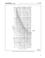
the time-current characteristic (Figure 7, page 16). A
1% variation in the 1.30 times tap value current
(including measuring instrument deviation) will
change the nominal operating time by approximately
4%. If the operating time at 1.3 times tap value is not
within these limits, a minor adjustment of the control
spring will give the correct operating time without any
undue effect on the minimum pick-up of the relay.
This check is to be made after the 2 times tap value
adjustment has been completed.

Summary of Contents for COV Series

Page 1: ...s a flux which divides and returns through the outer legs A shading coil causes the flux through the left leg to lag the main pole flux The out of phase fluxes thus produced in the air gap cause a contact closing torque The electromagnet for the COV 11 relay has a main coil consisting of a tapped primary winding Two iden tical coils on the outer legs of the lamination structure are connected to th...

Page 2: ...rolled Overcurrent Relay Sub 4 183A047 Sub 6 183A048 Figure 1 Internal Schematic of the COV Relay in the Type FT 21 Case Figure 2 Internal Schematic of the COV Relay with the Indicating Instantaneous Trip Unit in the Type FT 21 Case ...

Page 3: ... aluminum cylinder assembled to a molded hub which holds the shaft The shaft has removable top and bottom jewel bearings The shaft rides between the bottom pin bearing and the upper pin bearing with the cylinder rotating in an air gap formed by the electromagnet and the magnetic core The stops for the moving ele ment contact arm are an integral part of the bridge The bridge is secured to the elect...

Page 4: ... time dial position or by tap setting and a specific time of operation at some current mul tiple of the tap setting e g 4 tap setting 2 time dial position or 4 tap setting 0 6 seconds at 6 times tap value current To provide selective circuit breaker operation a mini mum coordinating time of 0 3 seconds plus breaker time is recommended between the relay being set and the relays with which coordinat...

Page 5: ...el panel mounting or to the terminal stud furnished with the relay for thick panel mounting The terminal stud may be easily removed or inserted by locking two nuts on the stud and then turning the proper nut with a wrench For detail information on the FT case refer to Instruc tion Leaflet 41 076 6 0 ADJUSTMENTS AND MAINTENANCE The proper adjustments to insure correct operation of this relay have b...

Page 6: ... that the 1 30 times tap value current be maintained accurately The main taining of this current accurately is necessary because of the steepness of the slope of the time current characteristic Figure 7 page 16 A 1 vari ation in the 1 30 times tap value current including measuring instrument deviation will change the nominal operating time by approximately 4 Table 1 shows the time curve calibratio...

Page 7: ...on the time dial when the stationary contact has moved through approximately one half of its normal deflection Therefore with the stationary contact resting against the backstop the index mark is offset to the right of the O mark by approximately 020 The placement of the various time dial positions in line with the index mark will give operating times as shown on the respective time current curves...

Page 8: ...nit is made as follows With the moving contact in the normally closed position i e against the left stop on bridge screw in the stationary contact until both con tacts just close as indicated by a neon lamp in the contact circuit Then screw the stationary contact in towards the moving contact an addi tional one half turn The clamp holding the stationary contact housing need not be loosened for the...

Page 9: ...67 3 96 21 114 325 1 0 4 1 88 66 4 07 21 4 122 360 1 5 5 7 88 62 4 19 23 2 147 462 2 0 6 8 88 60 4 30 24 9 168 548 2 5 7 7 88 58 4 37 26 2 180 630 2 6 2 8 230 67 3 88 21 110 308 2 5 8 8 230 66 3 90 21 6 118 342 3 9 7 230 64 3 93 22 1 126 381 3 5 10 4 230 63 4 09 23 1 136 417 4 11 2 230 62 4 12 23 5 144 448 5 12 5 230 59 4 20 24 8 162 540 6 13 7 230 57 4 38 26 5 183 624 4 12 4 16 460 65 4 00 22 4 1...

Page 10: ...174 552 2 5 7 7 88 56 4 38 25 9 185 640 2 6 2 8 230 66 4 06 21 3 111 306 2 5 8 8 230 63 4 07 21 8 120 342 3 9 7 230 63 4 14 22 5 129 366 3 5 10 4 230 62 4 34 23 4 141 413 4 11 2 230 61 4 34 23 8 149 448 5 12 5 230 59 4 40 25 2 163 530 6 13 7 230 58 4 62 27 183 624 4 12 4 16 460 64 4 24 22 8 129 392 5 18 8 460 61 4 30 24 2 149 460 6 19 3 460 60 4 62 25 9 168 540 7 20 8 460 58 4 69 27 3 187 626 8 22...

Page 11: ... 5 200 675 2 5 7 7 88 53 2 74 24 8 228 800 2 6 2 8 230 70 2 38 21 136 360 2 5 8 8 230 66 2 40 21 1 142 395 3 9 7 230 64 2 42 21 5 149 430 3 5 10 4 230 62 2 48 22 157 470 4 11 2 230 60 2 53 22 7 164 500 5 12 5 230 58 2 64 24 480 580 6 13 7 230 56 2 75 25 2 198 660 4 12 4 16 460 68 2 38 21 3 146 420 5 18 8 460 63 2 46 21 8 158 480 6 19 3 460 60 2 54 22 6 172 550 7 20 8 460 57 2 62 23 6 190 620 8 22 ...

Page 12: ...48 13 95 160 0 610 2 6 2 0 7 0 230 32 073 6 30 74 0 264 2 5 7 8 230 30 0 78 7 00 78 5 285 3 0 8 3 230 27 0 83 7 74 84 0 309 3 5 9 0 230 24 0 88 8 20 89 0 340 4 0 10 0 230 23 0 96 9 12 102 0 372 5 0 11 0 230 20 1 07 9 80 109 0 430 6 0 12 0 230 20 1 23 11 34 129 0 504 4 12 4 0 14 460 29 0 79 7 08 78 4 296 5 0 16 460 25 0 89 8 00 90 0 340 6 0 17 460 22 1 02 9 18 101 4 378 7 0 18 460 20 1 10 10 00 110...

Page 13: ...41 116K 13 Type COV Voltage Controlled Overcurrent Relay Sub 3 418246 Figure 4 Typical 50 and 60 Hz Time Curves of COV 6 Overcurrent Unit ...

Page 14: ...41 116K 14 Type COV Voltage Controlled Overcurrent Relay Sub 3 418247 Figure 5 Typical 50 and 60 Hz Time Curves of COV 7 Overcurrent Unit ...

Page 15: ...41 116K 15 Type COV Voltage Controlled Overcurrent Relay Sub 4 418248 Figure 6 Typical 50 and 60 Hz Time Curves of COV 8 Overcurrent Unit ...

Page 16: ...41 116K 16 Type COV Voltage Controlled Overcurrent Relay Sub 2 418249 Figure 7 Typical 50 and 60 Hz Time Curves of COV 9 Overcurrent Unit ...

Page 17: ...41 116K 17 Type COV Voltage Controlled Overcurrent Relay 288B655 Sub 2 Figure 8 Typical Time Curves of COV 11 Overcurrent Unit 50 60 Hertz ...

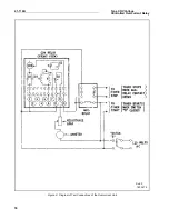
Page 18: ...41 116K 18 Type COV Voltage Controlled Overcurrent Relay 183A172 Sub 2 Figure 9 Diagram of Test Connections of the Overcurrent Unit ...

Page 19: ...41 116K 19 Type COV Voltage Controlled Overcurrent Relay 183A171 Sub 5 Figure 10 External Schematic of the Type COV Relay on a Generator ...

Page 20: ...ype COV Voltage Controlled Overcurrent Relay 184A471 Sub 3 Figure 11 Relay Types COV 6 COV 7 COV 8 COV 9 COV 11 Voltage Controlled Overcurrent Relay Double Trip with Indicating Instantaneous Trip in Type FT21 Case ...

Page 21: ...41 116K 21 Type COV Voltage Controlled Overcurrent Relay 184A400 Sub 2 Figure 12 Relay Types COV 6 COV 7 COV 8 COV 9 Voltage Controlled Overcurrent Relay Double Trip In TypeFT 21 Case ...

Page 22: ...41 116K 22 Type COV Voltage Controlled Overcurrent Relay NOTES ...

Page 23: ...41 116K 23 Type COV Voltage Controlled Overcurrent Relay NOTES ...

Page 24: ...rcurrent Relay ABB Automation Inc 4300 Coral Ridge Drive Coral Springs Florida 954 752 6700 Printed in U S A visit our website at www abbus com papd 57 D 7901 Sub 17 Figure 13 Outline and Drilling Plan for the Type COV Relay in Type FT 21 Case ...

Reviews: