


QUICK START GUIDE
Page 4
© 2021 ABB. All rights reserved.
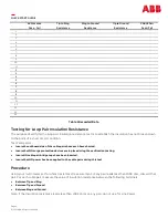
Testing for Loop Pair Insulation Resistance
The purpose of verifying the loop pair insulation resistance test is to establish the insulation has not broken down
to the point of a short circuit condition.
Test Parameters:
•
Insure the outboard side of the cable pairs have each been shorted.
•
Insure that NO surge protection devices are in place during the verification testing.
•
Insure NO cable pair bridge taps have been inserted.
•
Insure that NO power has been applied to the cable pairs during this test.
AC Presence
Pass
-
Fail
Tip to Ring
Resistance
Ring to Ground
Resistance
Tip to Ground
Resistance
CABLE Pair
Pass/Fail
1
2
3
4
5
6
7
8
9
10
11
12
13
14
15
16
17
18
19
20
21
22
23
24
25
Procedure
Using your multi
-
meter set for ohms (resistance) measurement. IF any pair reads less than 100K ohm, discard that
pair. For each cable pair, measure the value of insulation resistance between the following terminals.
•
Between Tip and Ring
•
Between Tip and Ground
•
Between Ring and Ground
Note: If the insulation resistance reads less than 100K ohms on any pair, do not use for Line Power.
Table 1 Recorded Data


