Page 99
© Copyright 2021 ABB. All rights reserved.
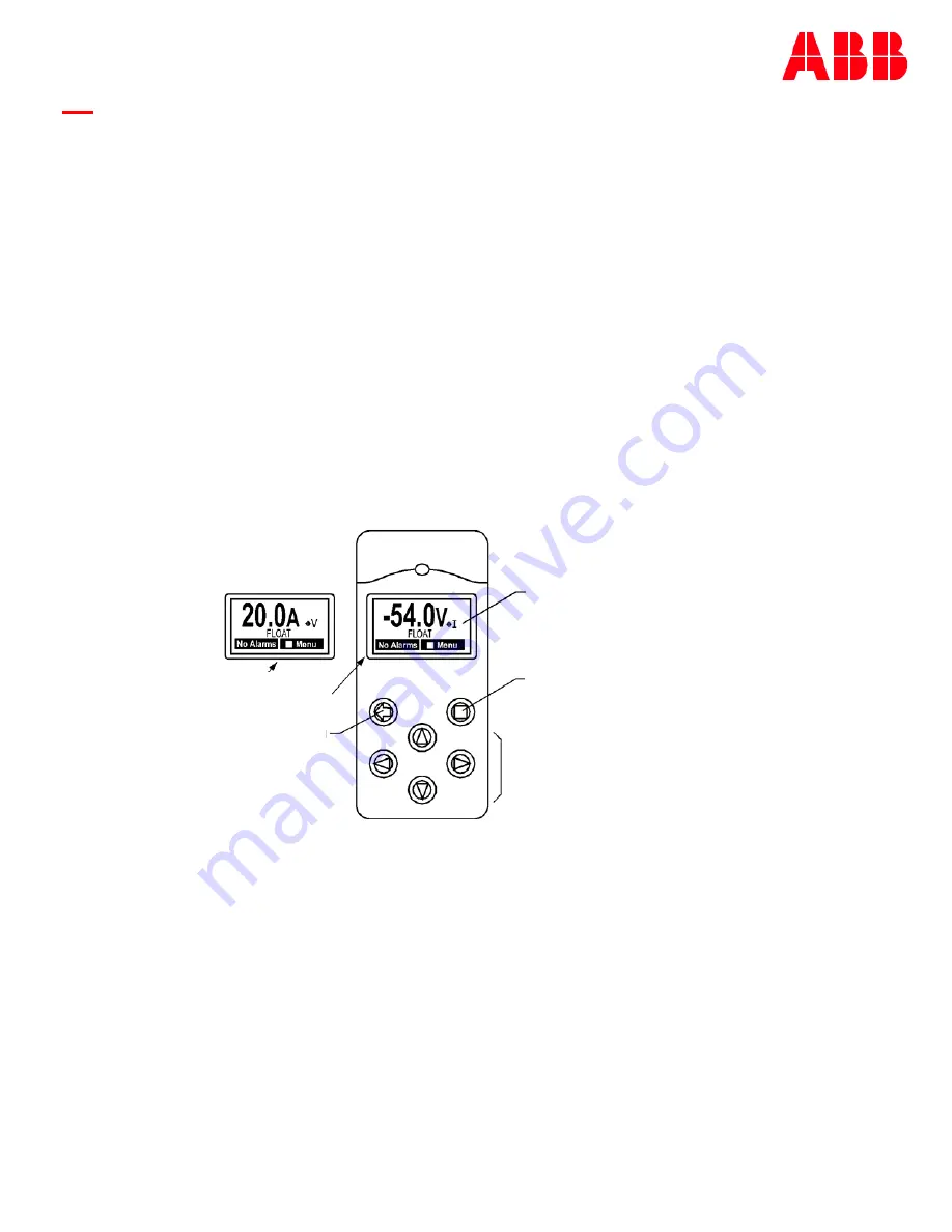
Figure 7
-
1: QS841A Controller Faceplate
7B QS841A System Controller
Overview
The QS841A controller is the integrated network controller option that can be custom configured for a
specific system or customer need. It provides system monitoring and control features, as well as office
alarm outputs from rectifiers, LVD boards, and remote modules.
This section describes the controller features, functions and alarms from perspective of a user utilizing
the front panel display. All these features are available through Web pages accessible from the Ethernet
port. The controller content in the web pages versus the front panel is arranged differently due to the
available large space that comes with using a monitor screen. However, the majority of the information
content, commands, and configurable items remain the same as those on the front panel. This section
focuses on describing the controller from the front panel perspective which is applicable to respective
feature implementation in the web pages.
Controls and Display
Figure 7
-
1 shows the front panel controls and display of the controller.
The backlight of the four
-
line LCD display changes color to reflect the system alarm status as follows:
Green
Normal
Amber
Minor Alarms Present
Red
Major Alarms Active
The up and down arrow keys can be used to adjust screen contrast when the controller is displaying
the default screen. Contrast adjustment is also available through the menus at
Menu>Configuration>System Settings. At the default menu, the left and right arrows are also used to
toggle the display from displaying the system voltage or the system load current.
Otherwise, the left and right arrow keys are used to navigate the menus and the up and down arrow
keys are used to change values when configuring the system. A black box highlighting a menu item
indicates that the item has sub
-
menus.
Display
Showing Default Screen
Display Menus
Save Changes
Refresh
Arrow Keys
Navigate Menus (up, Down left right)
Adjust Values during Configuration
Previous Menu
Amps Display
Volts Display
Summary of Contents for CPS6000
Page 6: ...Page 6 Copyright 2021 ABB All rights reserved This page intentionally left blank Jl ll ll ...
Page 36: ...Page 36 Copyright 2021 ABB All rights reserved This page intentionally left blank Jl ll ll ...
Page 82: ...Page 82 Copyright 2021 ABB All rights reserved This page intentionally left blank Jl ll ll ...
Page 98: ...Page 98 Copyright 2021 ABB All rights reserved This page intentionally left blank Jl ll ll ...
Page 124: ...Page 124 Copyright 2021 ABB All rights reserved This page intentionally left blank ...
Page 146: ...Page 146 Copyright 2021 ABB All rights reserved This page intentionally left blank ...
Page 152: ...Page 152 Copyright 2021 ABB All rights reserved This page intentionally left blank ...
Page 174: ...Page 174 Copyright 2021 ABB All rights reserved This page intentionally left blank ...
Page 188: ...Page 188 Copyright 2021 ABB All rights reserved This page intentionally left blank ...
Page 192: ...Page 192 Copyright 2021 ABB All rights reserved This page intentionally left blank ...
Page 196: ...Page 196 Copyright 2021 ABB All rights reserved This page intentionally left blank ...
Page 198: ...Page 198 Copyright 2021 ABB All rights reserved This page intentionally left blank ...


