Summary of Contents for CR Series

Page 1: ...t on the reli the front of the switch which allows the operation indi ability of the zero sequence polarizing current or voltage cator target to drop The target is reset from the outside of for all ground faults with all power system variations the case by a push rod located at the bottom of the cover Where neither alone is generally reliable for all ground faults but one or the other is always pr...

Page 2: ...t onary Contact pressure spring 3 Magnef c adjusting plugs 4 Upper bear ng screw Mov ng element assembly 6 Spr ng adfaster clamp 7 Currenf 8 as Vane 2 F g 7 Type CF Relay Without Case I Directional Unit D 2 Overcurrent Unit CO 3 lndlcatlng Con tactor Switch ICS 5 Courtesy of NationalSwitchgear com ...

Page 3: ... Fig 3 Time Overcurrent Unit Front View 1 Tap Block 2 Time Dial 3 Control Spring Assembly 4 Disc 5 Stationary Contact Assembly 6 Magnetic Plugs 7 Permanent Magnet Fig 4 Indicating Instantaneous Trip Unit IIT 3 Courtesy of NationalSwitchgear com ...

Page 4: ...e polarizing cir cuit flux and the operating circuit flux Mechanically the directional unit is composed of four basic components a die cast aluminum frame an electro magnet a moving element assembly and a molded bridge The frame serves as the mounting structure for the mag netic core The magnetic core which houses the lower pin bearing is secured to the frame by a locking nut The bear ing can be r...

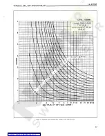
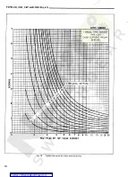
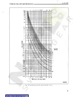
Page 5: ...d 0 5 to 2 5 ampere range relays These relays may have either single or double circuit closing contacts for tripping either one or two circuit breakers The time vs current characteristics are shown in Figs 13 to 19 These characteristics give the con tact closing time for the various time dial settings when the indicated multiples of tap value current are applied to the relay The directional unit s...

Page 6: ...ion is made by connecting the lead located in front of the tap block to the desired setting by means of the connecting screw C Indicating Instantaneous Trip IIT The current polarized directional unit of the type CRD relay onerates on residual currents while the potential polarized directional unit of the type CRD relay operates on residual voltage and residual cur rent See Fig 24 The core screw mu...

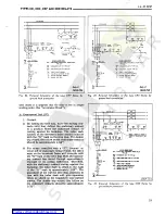
Page 7: ...NTANEOUS POLAR TV AS SNOW HE DIRECTIONAL UNIT CONTACTS CLOSE Sub 5 57D4540 Sub 6 57D4520 Fig 9 Internal Schematic of single trip directional control Fig 10 Internal Schematic of single trip directional con relay Type CR with Indicating Instantaneous Trip Unit in Type FT21 Case trol relay Type CRC with Indicating instantaneous Trip Unit in Type FT21 Case INTERNAL SCHEMATIC 4 fC INDICATING A C CONTA...

Page 8: ...262 2 0 3 1 38 7 800 5 13 2 5 110 55 39 8 920 4 0 280 110 51 5 37 3 0 4 4 312 42 8 1008 2 6 110 5 53 3 5 4 8 47 42 8 329 1120 110 45 5 72 4 0 5 2 360 46 0 1216 5 0 5 6 41 5 90 110 50 3 420 1500 6 0 37 6 54 6 0 110 54 9 474 1800 65 230 4 92 4 0 7 3 39 1 268 848 230 50 5 20 5 0 8 0 42 0 305 1020 8 8 230 47 5 34 6 0 330 44 1 1128 4 12 7 0 9 6 230 46 5 53 1260 45 8 364 230 8 0 10 4 43 5 86 49 9 1408 4...

Page 9: ...R 7 CRC 7 CRP 7 CRO 7 OVERCURRENT UNITS VOLT AMPERESft At 3 Times At 10 Times Tap Value Tap Value Tap Value Current Current Current At 20 Times Tap Value Current One Second Rating t Amperes Power Factor Angle f At Continuous Rating Amperes Ampere Range Tap 278 103 20 7 3 88 68 88 0 5 0 6 0 8 0 5 2 5 1 0 1 5 2 0 2 5 2 7 288 107 20 9 3 93 67 88 3 1 320 114 21 1 3 93 66 88 3 7 122 356 21 6 4 00 88 64...

Page 10: ... UNITS VOLT AMPERES tt AT 20 TIMES TAP VALUE CURRENT CONTINUOUS RATING AMPERES ONE SECOND POWER RATING t FACTOR TAP VALUE AMPERES ANGLER CURRENT AT 3 TIMES AT 10 TIMES TAP VALUE TAP VALUE CURRENT CURRENT AT AMPERE RANGE TAP 6 54 250 0 5 56 36 0 72 71 8 1 7 267 6 80 75 0 0 6 1 9 56 0 75 34 7 46 0 8 84 0 298 2 2 56 30 0 81 2 5 0 5 2 5 8 30 93 1 330 1 0 56 0 89 27 115 5 136 3 160 0 411 1 5 56 10 04 1...

Page 11: ... BURDEN VOLT AMPEREStt At 20 Times Minimum Tap Value Current At At 3 Times At 10 Times Minimum Minimum Tap Value Tap Value Current Continuous One Second Power Rating Factor Amperes Angle f Minimum Tap Value Current Relay Range Rating Type Amps Amperes Current 34 5 0 44 4 08 230 182 0 2 6 10 48 0 CR 0 53 5 0 280 25 0 236 0 4 12 12 59 2 230 0 30 14 2 44 0 0 5 2 5 3 3 0 033 CRC 0 58 5 28 230 42 5 58 ...

Page 12: ...ts should be approximately 1 32 The proper adjustments to insure correct operation of this relay have been made at the factory Upon receipt of the relay no customer adjustments other than those covered under SETTINGS should be required For relays which include an indicating instantan eous trip unit STT the junction of the induction and indicating instantaneous trip coils is brought out to switch j...

Page 13: ...I L 41 131P TYPES CR CRC CRP AND Cku RELAYS Q Fig 13 Typico T Curves For Re oys With CO 2 Units me 13 Courtesy of NationalSwitchgear com ...

Page 14: ...TYPES CR CRC CRP AND CRD RELAYS F i g 14 Typical T i m e Curves For Relays With CO 5 U n i t s 14 Courtesy of NationalSwitchgear com ...

Page 15: ...I L 41 131P TYPES CR CRC CRP AND CRD RELAYS Fig 15 Typical time curves for relays with CO 6 units 15 Courtesy of NationalSwitchgear com ...

Page 16: ...TYPES CR CRC CRP AND CRD RELAYS Fig 16 Typical time curves for relays with CO 7 units 16 Courtesy of NationalSwitchgear com ...

Page 17: ...I L 41 131P TYPES CR CRC CRP AND CRD RELAYS Fig 77 Typical time curves for tel ays with CO 8 units 17 Courtesy of NationalSwitchgear com ...

Page 18: ...TYPES CR CRC CRP AND CRD RELAYS Typical time curves for relays with CO 9 units Fig 18 18 Courtesy of NationalSwitchgear com ...

Page 19: ...I L 41 131P TYPES CR CRC CRP AND CRD RELAYS TIME OUt SETTING 288B655 Fig 79 Typical time curves for relays with CO 7 7 units 19 Courtesy of NationalSwitchgear com ...

Page 20: ... Unit IIT Routine Maintenance All relays should be inspected and checked periodically to assure proper operation Generally a visual inspection should call attention to any noticeable changes A mini mum suggested check on the relay system is to close the contacts manually to assure that the breaker trips and the target drops Then release the contacts and observe that the reset is smooth and positiv...

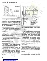
Page 21: ...g con tacts until they deflect the stationary contact to a position where the stationary contact is resting against its backstop The index mark located on the movement frame should coincide with the O mark on the time dial For double trip relays the follow on the stationary contacts should be approximately 1 64 g fr sjs HF 67N 67N in H 3 5 PHASE RELAYS IR3TALL JUMPERS AS SNOWR IF POTENTIAL POLARI2...

Page 22: ...me Curve Calibration Install the permanent magnet Apply the indicated current per Table 2 for the per manent magnet adjustment e g CR 8 2 times tap value and measure the operating time Adjust the permanent magnet keeper until the operating time corresponds to the value of Table 2 B Indicating Contactor Switch Unit ICS Close the main relay contacts and pass sufficient d c current through the trip c...

Page 23: ...een shop adjusted for optimum follow and this adjustment should not be disturbed b The polarizing circuit of the current polarized relays CRC and CRD current polarized unit are open circuited Upon completion of either a or b current is applied to the operating circuit terminals as per Table 4 Plug adjustment is then made per Table 4 such that the spurious torques are reversed The plugs are held in...

Page 24: ...quantities are input quantities at the relay terminals ffMaximum torque angle ff f For relays rated 240 volt apply 2 volt TABLE 4 DIRECTIONAL UNIT CALIBRATION Current Amperes Both Plugs In Condition Relay Rating Adjustment 0 5 to 2 5 2 to 6 Right Front View Plug Screwed Out Until Spurious Torque is Reversed Spurious Torque In Contact Closing Direction Left Front View 40 4 to 12 80 0 5 to 2 5 2 to ...

Page 25: ... MTG 3 f 1 344 34 14 r 2 688 68 28 S 30 23 PJA m S 5 375 136 53 I t 0 I 6C 397 250 A 6 35 L03I I 03I t 1 031 I 26 19 26 19 26 19 I 375 W 03 I 26 19 SJ5S PANEL CASE i A I 10 254 y A 9 3 5 t I NTERNAL EXTERNAL TOOTHED WASHERS 1 3 4645 1 2 0 1 1 504 190 32 SCREW FOR THICK PANELS USE 190 32 STUDS 9 fi I 2 JU 1 Sfr 516 0311 750 TERMINAL NUMBER OIA f niA l TERMINAL AND w MOUNTING DETAILS 19 05 10 HOLES ...

Page 26: ... 111 13 2 688 68 28 _ 5 375 036 53 I 4 K0I6 397 250 r 6 35 M 03I KL03I 1 031 t 1 031 1 26 19 26 19 26 19 26 19 I 4 375 III 13 375 e 9 53 R PANEL CASE i f 1 0 25 4 t B 3 5 I 9 INTERNAL EXTERNAL TOOTHED WASHERS Lgj3 46 04 1 2 0 1 1 190 32 SCREW S FOR THICK U S E 190 32 STUDS 50 8 m 2 4 6 8 1 PANELS V v i Sfr 19 05 D A 03 11 10 HOLES OR I 03l H 03l 1031 K03I CUTOUT 26 19 26 19 26 19 26 19 PANEL DRILL...

Page 27: ... CAT ING INSTANTANEOUS UNIT CO ICS I IT Hh RED HANDLE TEST SWITCH r o i CURRENT TEST JACK CHASSIS OPERATED SHORTING SWITCH l O J 1 _ b 7 5 9 1 2 4 TERMINAL FRONT VIEW WITH RELATIVE INSTANTANEOUS POLARITY AS SHOWN THE DIRECTIONAL UNIT CONTACTS CLOSE Sub 1 9657A31 Figure 27 Internal Schematic 71 Courtesy of NationalSwitchgear com ...

Reviews: