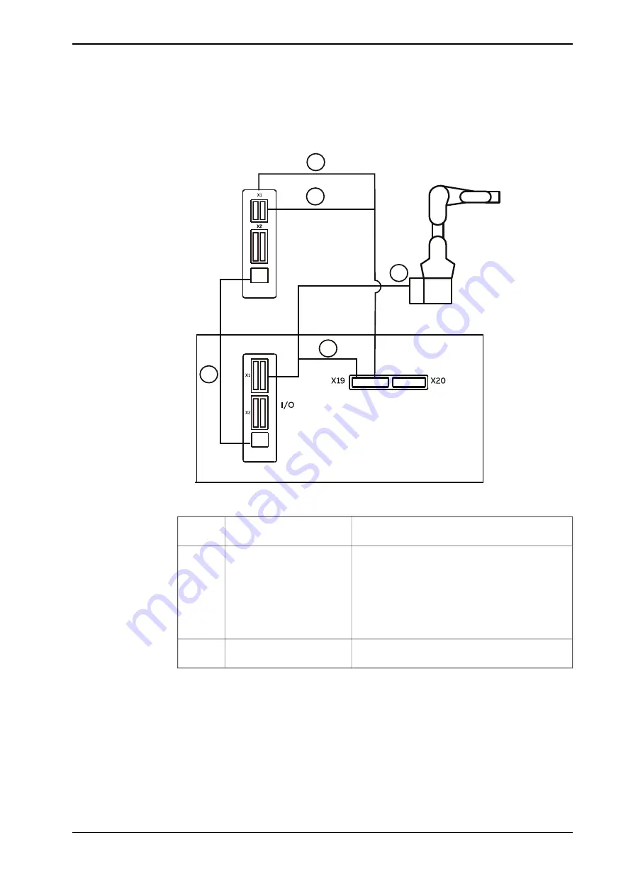
The following figure illustrates the connection among manipulator, controller with
base I/O device configured and the safety I/O device.
DSQC 1042
X3
DSQC 1030
X3
Controller
1
2
3
5
4
xx2200001154
Between X3 connectors on DSQC1030 and on
DSQC1042
Ethernet connection
1
Using CP/CS cable to connect,
Lamp unit cabling
2
•
X1 connector on DSQC1030
Pins GND, DO1, DO2 and DO3 are occupied
for lamp unit
•
X19 connector on controller
Pins 1 and 2 are occupied for lamp unit
•
R1.C1 connector on manipulator base
Between X4 connector on DSQC1030 and X19
connector on controller
Power connection
3
For details about the I/O module models, see
Application manual - Scalable I/O
.
Product manual - CRB 1300
105
3HAC083111-001 Revision: B
© Copyright 2022-2023 ABB. All rights reserved.
3 Installation and commissioning
3.5.2 Customer connections
Continued
Summary of Contents for CRB 1300
Page 1: ...ROBOTICS Product manual CRB 1300 ...
Page 50: ...This page is intentionally left blank ...
Page 662: ...This page is intentionally left blank ...
Page 690: ...This page is intentionally left blank ...
Page 704: ...This page is intentionally left blank ...
Page 720: ...This page is intentionally left blank ...
Page 725: ......


