3.7.5.3 Configuration of one PROFIsafe-based laser scanner (RobotWare 7.10 or
later and OmniCore acting as Master)
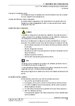
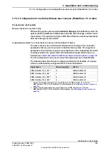
Preparing the robot system
Required options for system setup
When setting up the system using
Installation Manager
in RobotStudio, select the
options
[3020-1] PROFINET Controller
,
[3023-1] PROFIsafe Controller
,
[3043-3]
SafeMove Collaborative
and
[3051-1] Profisafe Package
, and the correct robot
variant. The option
Drive System IRB Small Robot
is selected automatically after
the robot type is determined.
Configuring supported parameters of the robot system
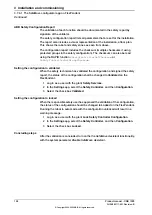
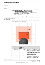
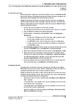
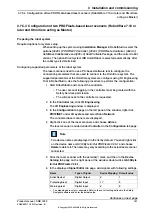
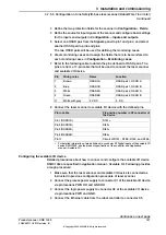
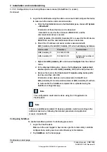
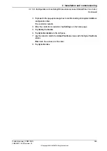
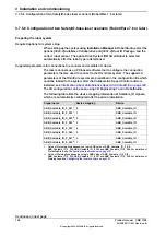
The laser scanner needs to use a PC-based software tool to configure the
connection parameters that are used to connect to the OmniCore system. The
supported parameters of the OmniCore system are configure using I/O Engineering
Tool in RobotStudio. Use the following procedure to perform the configuration:
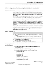
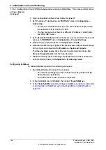
1 Start RobotStudio and connect the controller.
•
The user account logging in the controller must be granted with the
Safety Services permission.
•
The write access to the controller is requested.
2 In the
Controller
tab, click
I/O Engineering
.
The
I/O Engineering
window is displayed.
3 In the
Configuration
tab page on the left pane of the window, right-click
PROFINET
under
I/O system
and select
Scan Network
.
The connected laser scanner is displayed.
4 Right-click on the laser scanner and choose
Add as
.
The laser scanner is added under
Controller
in the
Configuration
tab page.
Note
Two device names are displayed in the list by default. You shall right-click
on the device name
mS3 12Byte In/Out PROFIsafe V2.6.1
and choose
Delete
to delete it. The name may vary according to the actual laser scanner
connected.
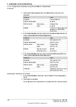
5 Click the laser scanner with the asterisk(*) mark, and then in the
Device
Catalog
tab page on the right pane of the window, double-click
mS3 6Byte
In/Out PROFIsafe V2.6.1
.
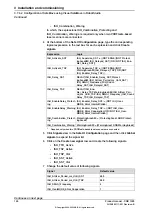
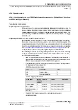
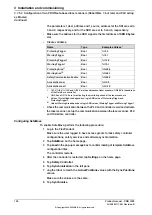
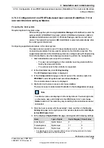
6 In the displayed
Signal Editor
tab page, add signals with following settings.
Default value
Device Mapping
i
Type of Signal
Name
1
8
Digital Output
ActiveDevice1
0
17
Digital Input
ProtectingArea1
0
8
Digital Input
WarningArea1
i
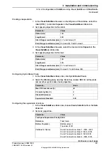
The mappings are only for examples. Refer to the cut-off setting defined in the
Safety
Designer
software and enter the actual value.
Continues on next page
Product manual - CRB 1300
137
3HAC083111-001 Revision: B
© Copyright 2022-2023 ABB. All rights reserved.
3 Installation and commissioning
3.7.5.3 Configuration of one PROFIsafe-based laser scanner (RobotWare 7.10 or later and OmniCore
acting as Master)
Summary of Contents for CRB 1300
Page 1: ...ROBOTICS Product manual CRB 1300 ...
Page 50: ...This page is intentionally left blank ...
Page 662: ...This page is intentionally left blank ...
Page 690: ...This page is intentionally left blank ...
Page 704: ...This page is intentionally left blank ...
Page 720: ...This page is intentionally left blank ...
Page 725: ......

