I.L. 41-201S
4
voltage. With application of voltages greater than
tap value voltage, the moving contact moves to
close the front contact in a time as shown by the
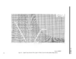
right-hand curves of either Figures 15 or 16.
When the relay is used as an undervoltage relay,
the moving contact is made with the stationary
front contact for values of applied voltage greater
than tap value voltage. With the application of
voltages less than tap value voltage, the moving
contacts moves to close the back contact in a
time as shown on the left-hand curves of either
Figures 15 or 16.
3.3.
CV-8 Overvoltage Relay
The low pickup CV-8 overvoltage relay is avail-
able with the following ratings.
The minimum voltage required to just close the
CV-8 contacts is typically 8% of the continuous
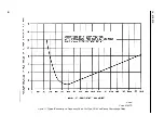
voltage. Typical operating times of the type CV-8
relay are shown in Figure 10a and Figure 10b.
An adjustable 5.4 to 20 volt relay with a 67 volt
continuous and a 16 to 40 volt relay with a con-
tinuous of 199 volts is also available. However,
the operate times of the adjustable CV-8 relay
will differ from Figure 10a and will depend on the
pickup setting. Figure 10b applies when the
resistor is set for 30% of continuous voltage rat-
ing.
3.4.
Trip Circuit
The main contacts will close 30 amperes at 250
volts dc and the seal-in contacts of the indicating
contactor switch (ICS) will carry this current long
enough to trip a circuit breaker.
The indicating contactor switch (ICS) has two
taps that provide a pickup setting of 0.2 or 2 A.
To change taps requires connecting the lead
located in front of the desired setting by means
of a screw connection.
Continuous Rating
2 Minute Rating
67 volts
199 volts
140 volts
300 volts
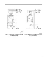
Figure 4.
Internal Schematic of the Double Trip Type CV
Undervoltage Relays in Type FT-11 Case. For
the Single Trip Relays the circuits associated
with Terminal 2 are omitted.
Sub2
182A725
Figure 5.
Internal Schematic of the Type CV Over or
Undervoltage Relay in Type FT-11 Case.
Sub 2
182A727
Summary of Contents for CV-1
Page 2: ......


