Type CWC and CWP Directional Ground Relay
41-242.2F
5
plate. The upper pole tap plate is marked x 1 and x 4
Product. The last four values are obtained by using
the x 4 tap with the four lower pole taps.
Typical 60 Hertz time-product curves for the type
CWC relay are shown in Fig. 9. These curves are
taken at maximum torque which occurs with the cur-
rents in phase. For residual and Ground currents out
of phase the relay operating time may be obtained
by determining the operating time corresponding to
the product P' - P Cos Ø, where P is the actual relay
product in amperes squared, and Ø is the angle
between the residual and polarizing currents.
The limits for which these curves are accurate within
± 7% are shown in Fig. 10.
3.2
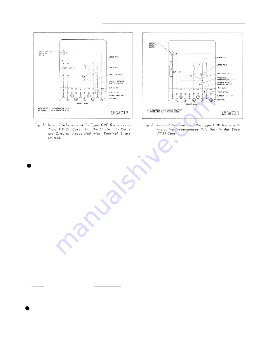
TYPE CWP RELAY
The type CWP relay taps are on the upper pole cur-
rent coil. They represent the minimum pickup prod-
uct of current times voltage at maximum torque
when the current lags the voltage by 60 °. The range
and taps are:
Product
Range
Tap Markings
20
-
150
20 30 40 50 75 100
150
75
-
600 75 100 150 200 300 400 600
Typical 60 Hertz time product curves for the type
CWP relay are shown in Fig. 11. These curves are
taken at maximum torque which occurs with the cur-
rent lagging the voltage 60 °. For currents not lag-
ging by this angle, the relay tripping time may be
obtained by determining the operating time corre-
sponding to the product p' = P Cos (60 ° - 6), where
P is the actual relay V.A. product and a is the angle
the current lags the voltage. The curves are accurate
within ± 7% if the multiple of tap product does not
exceed the voltage on the relay coil.
3.3
TRIP CIRCUIT
The main contacts will safely close 30 amperes at
250 volts d-c and the seal-in contacts of the indicat-
ing contactor switch will safely carry this current long
enough to trip a circuit breaker.
The indicating instantaneous trip contacts will safely
close 30 amperes at 250 volts d-c, and will carry this
current long enough to trip a breaker.
The indicating contactor switch has two taps that
provide a pickup setting of 0.2 or 2 amperes. To
change taps requires connecting the lead located in
front of the tap block to the desired setting by means
of a screw connection.
3.4
TRIP CIRCUIT CONSTANT
Indicating Contactor Switch (ICS)
0.2 ampere tap 6.5 ohms d-c resistance
2.0 ampere tap 0.15 ohms d-c resistance
*
*
Summary of Contents for CWC
Page 2: ...41 242 2F Type CWC and CWP Directional Ground Relay 2 ...
Page 3: ...Type CWC and CWP Directional Ground Relay 41 242 2F 3 ...
Page 7: ...Type CWC and CWP Directional Ground Relay 41 242 2F 7 ...
Page 8: ...41 242 2F Type CWC and CWP Directional Ground Relay 8 ...
Page 15: ...Type CWC and CWP Directional Ground Relay 41 242 2F 15 THIS PAGE RESERVED FOR NOTES ...


