background image

ABB Instrumentation

User Guide

DATUM L160
Wall-/Pipe-Mounted
Universal Level Indicator

888888

DATUM

L160

Summary of Contents for DATUM L160

Page 1: ...ABB Instrumentation User Guide DATUM L160 Wall Pipe Mounted Universal Level Indicator 888888 DATUM L160 ...

Page 2: ...to health the following points must be noted 1 The relevant sections of these instructions must be read carefully before proceeding 2 Warning labels on containers and packages must be observed 3 Installation operation maintenance and servicing must only be carried out by suitably trained personnel and in accordance with the information given 4 Normal safety precautions must be taken to avoid the p...

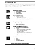
Page 3: ...on Mode Levels 3 and 4 Accessing the configuration levels Level 3 Hardware assignment and input type Alarm types and hysteresis Operator functions Digital input and serial communications Level 4 Ranges and passwords Installation Siting Mounting Electrical connections 8 Symbol Identification and Section Contents This manual is divided into five sections which contain all the information needed to i...

Page 4: ... 11 3 SET UP MODE 12 3 1 Introduction 12 3 2 Set Up Level Level 2 13 4 CONFIGURATION MODE 16 4 1 Introduction 16 4 2 Accessing the Configuration Mode 18 4 3 Basic Hardware and Indicator Functions Level 3 18 4 3 1 Hardware Assignment and Input Type 18 4 3 2 Alarms 20 4 3 3 Operator Functions 25 4 3 4 Digital Input and Serial Communications 26 4 4 Ranges and Passwords Level 4 28 5 INSTALLATION 30 5 ...

Page 5: ... function keys and LED indicators are shown in Fig 1 1 tESt A1 A2 A3 Alarm LEDs secret till lit Function Keys Parameter advance Raise Lower Multi function key A1 A2 A3 tESt A1 A2 A3 2001 01 Displays shown during the start up procedure Displayed at startup for 3 seconds Software version and issue eg L160 2001 Issue 1 displayed for 3 seconds Display ...

Page 6: ...VEL1 100 1 CodE 0 Use to view a parameter setting or selection or select individual characters in a frame 123456 move between levels LEVEL1 LEVEL2 LEVELx 100 1 200 2 300 3 400 4 Press for a few seconds or select the top LEVEL frame from within a level Note This key also stores any changes made in the previous frame 1 DISPLAYS AND FUNCTION KEYS Fig 1 2 Use of Function Keys 1 2 Use of Function Keys ...

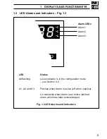
Page 7: ...lashing Level indicator is in the configuration mode see Section 4 2 A1 A2 and A3 Flashes when Alarm is active off when inactive Lit constantly when Alarm is an active latched alarm which has been acknowledged Fig 1 3 LED Alarms and Indicators Alarm 1 Alarm 2 Alarm 3 Alarm LEDs A1 A2 A3 ...

Page 8: ... output Contact the Service Organization Error Action Start up screen Displayed at system start up Calibration error Turn mains power off and on again if the error persists contact the ServiceOrganization Configuration error The configuration and or setup data for the instrument is corrupted Turn mains power off and on again if error persists check configuration setup settings A to D Converter fau...

Page 9: ...ted by the indicator functions which are selected during configuration of the instrument see Section 4 Note Only the operating frames relevant to the configured functions are displayed in Operator Mode The three indicator functions are Standard Level Indicator page 8 Level Indicator with Max Min Average page 9 Level Indicator with Volume Indication page 11 ...

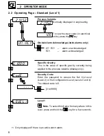
Page 10: ...he key Global Alarm Acknowledge latch alarms only UN ACK alarm unacknowledged ACK alarm acknowledged Specific Gravity This is the value of specific gravity currently being applied to the process variable display only Security Code Enter the password to access the Set Up Level Level 2 or the Configuration Level Levels 3 and 4 The default code is 0 0 to 9999 Level 1 Note To select this frame from an...

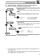
Page 11: ...p and can also be reset from a digital input see Section 4 3 4 rSt n 2145 3 UN ACK A 140 5 H150 2 1 Measured Level To view the input value in electrical units press the key Global Alarm Acknowledge latch alarms only UN ACK alarm unacknowledged ACK alarm acknowledged Average Value This is the mean average value of the process variable since the average was reset To reset the average value select rS...

Page 12: ...ect rSt Y then press the key rSt Y reset rSt n do not reset Minimum Value This is the minimum value of the process variable since the minimum was reset To reset the minimum value select rSt Y then press the key rSt Y reset rSt n do not reset Specific Gravity This is the value of specific gravity currently being applied to the process variable display only Security Code Enter the correct code to ac...

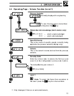
Page 13: ...ge latch alarms only UN ACK alarm unacknowledged ACK alarm acknowledged Specific Gravity This is the value of specific gravity currently being applied to the process variable display only Volume This is the current volume derived from the process variable Security Code Enter the correct code to access the Set Up Level Level 2 or the Configuration Level Levels 3 and 4 The default factory set code i...

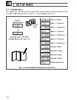
Page 14: ...ons 2 2 to 2 4 LEVEL1 LEVEL2 A1xx A1 HYSt A2xx A2 HYSt A3xx A3 HYSt A xxxx H xxxx L xxxx SPGrAV Level 2 Set Up Alarm 1 Trip Point Alarm 1 Hysteresis Alarm 2 Trip Point Alarm 2 Hysteresis Alarm 3 Trip Point Alarm 3 Hysteresis Average Value Maximum Value Minimum Value Specific Gravity Offset Adjustment Security Code 0 to 9999 default factory set code 0 Level 1 Operating Level Correct Code CodE x 0Ad...

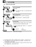
Page 15: ...gineering span per hour Alarm 1 Hysteresis Not applicable to A1 Fr and A1 Sr alarm type Process alarms engineering units Alarm 2 Trip Point Alarm type In engineering units or of engineering span per hour Alarm 2 Hysteresis Not applicable to A2 Fr and A2 Sr alarm type in engineering range Continued on next page 200 2 A1 hP 100 1 A2 LP LEVEL2 1 1 A1 HYSt 100 0 A2 HYSt 20 0 A3 hP 2 2 1 Not displayed ...

Page 16: ... reset from a digital input see Section 4 3 3 300 3 A3 hP 1 A1405 rSt n 3 4 34 6 A3 HYS 2 L130 8 Alarm 3 Trip Point Alarm type In engineering units or engineering span per hour Alarm 3 Hysteresis Not applicable to A3 Fr and A3 Sralarm type Process alarms engineering units Average Value This is the mean average value of the process variable input since the average was reset To reset the average val...

Page 17: ...inimum value of the level input since the minimum was reset To reset the minimum value select rSt Y then press the key rSt Y reset rSt n do not reset Specific Gravity Enter the specific gravity of the liquid to be measured Offset Adjustment An offset can be applied to the level input to enable spot calibration or the removal of system errors 10 of engineering range 1 The maximum and minimum values...

Page 18: ...shown in Fig 4 1 Level 3 is divided into four frames For most simple applications it is only necessary to set up the parameters in the first frame Note When in the Configuration Level All the l e d indicators flash All relays and logic outputs are turned off The analog output reverts to 0 4mA output level ...

Page 19: ...ngineering Range Low Retransmission Range High Retransmission Range Low Volume Constant Set Up Password Configuration Password MODBUS Address Hardware Configuration Alarms and Set Points Level 3 K L 0000 n J Operator Functions r 0000 S 0000 t 0000 P 0000 Digital Input and Serial Comms 4 CONFIGURATION MODE 4 1 Introduction Fig 4 1 Fig 4 1 Configuration Levels ...

Page 20: ...Level 3 4 3 1 Hardware Assignment and Input Type Fig 4 2 Level 3 Note To select this frame from anywhere in this level press and hold the key for a few seconds ABCD Settings The first character A B C or D identifies the parameter to be changed The current setting is indicated by a flashing letter Parameter options are shown in Fig 4 2 A Hardware configuration b Input type and range C Not applicabl...

Page 21: ...ce Source Source 1 A Alarm 1 Alarm 2 Alarm 3 IPFAIL ML 2 b Alarm 1 Alarm 2 Alarm 3 IPFAIL ML average U Custom Custom Custom Custom Custom A 1200 A Hardware Configuration ML Measured level IPFAIL Measured level failure only available if the appropriate option board is fitted b 1200 B Input Type and Range Configuration C 1200 D Process Variable Display Decimal Places d 1200 C Not Applicable Display ...

Page 22: ...he parameter to be changed The current setting is indicated by a flashing letter Parameter options are shown in Fig 4 5 E Alarm 1 type F Alarm 2 type G Alarm 3 type H Alarm hysteresis Note For fail safe operation active alarms denergize the relay and inactive alarms energize the relay For custom settings contact the local distributor Continued on page 22 F 0000 E 0000 G 0000 H 0000 P 0000 ...

Page 23: ...0 None 1 High Process 2 Low Process 3 High Latch 4 Low Latch 5 Fast Rate 6 Slow Rate F Alarm 2 Type Display 0 None 1 High Process 2 Low Process 3 High Latch 4 Low Latch 5 Fast Rate 6 Slow Rate Value in of engineering range 4 3 2 Alarms Figs 4 3 4 4 4 5 and 4 6 Fig 4 3 Alarm Types 4 CONFIGURATION MODE Note When custom alarm hysteresis is selected the alarm hysteresis values must first be set indivi...

Page 24: ...alue of zero is configured the alarm becomes inactive when the process variable value returns past the alarm trip point value If a positive or negative hysteresis value is configured the alarm becomes inactive when the process variable reaches the hysteresis point The hysteresis value is configured in engineering units e g if a hysteresis point five inches H2 0 below the alarm trip point is requir...

Page 25: ...variable is faster or slower than the configured alarm value Rate of change alarm values are configured as a of span change per hour The elapsed time period before the alarm condition is detected is dependant upon the configured alarm value This period can be calculated as follows The alarm remains active until the rate of change in the process variable returns to the non alarm condition The calcu...

Page 26: ...omes active when the process variable value rises above the high latch alarm trip point value or falls below the low latch alarm trip point value The latch alarm trip point values are configured in engineering units in the Set Up Level Level 2 The alarm remains active until it is acknowledged and the alarm process condition is removed The alarm can be acknowledged using the keys on the instrument ...

Page 27: ...ashing letter Available parameter options are shown in Fig 4 7 below J Not applicable K Not applicable L Operator Level frame enable n Operator Level math reset enable Note For custom settings contact the local distributor Continued on page 26 Fig 4 7 Operator Level Maths Reset Enable Parameter Max Min Average Volume Setting 0 1 2 3 4 5 6 7 Parameter Max Min Average Setting 0 1 L 0000 n 0000 ...

Page 28: ...digital input is operational Fig 4 8 Digital Functions 4 3 4 Digital Input and Serial Communications Fig 4 8 and 4 9 PRST Settings The first character P R S or T identifies the parameter to be changed The current setting is indicated by a flashing letter Parameter options are shown in Fig 4 8 P Digital input function r Analog input filter S Serial communications configuration t Serial communicatio...

Page 29: ...isplay 0 None 1 Average Max Min Reset 2 Front Panel Lockout 3 Alarm Acknowledge P Digital Input Function Display 0 0 seconds 1 1 second 2 2 seconds 5 5 seconds A 10 seconds B 20 seconds C 40 seconds D 60 seconds R Analog Input Filter 4 CONFIGURATION MODE Fig 4 9 Digital Functions and Serial Communications Configuration Note Settings for options P S and T are only available if the appropriate optio...

Page 30: ...e 100 0 metres 9999 to 99999 Low Value 0 0 metres 9999 to 99999 Retransmission Range Defines the engineering range to be retransmitted High 20mA output 9999 to 99999 in engineering units Low 4mA output 9999 to 99999 in engineering units Continued on next page 0 0 ENG HI 100 0 ENG LO LEVEL4 VOLCON 100 0 rEt HI 0 0 rEt LO 4 4 Ranges and Passwords Level 4 ...

Page 31: ...set 0 Configuration Password The password enables access to the configuration levels Levels 3 and 4 The Configuration password overides the setup password 0 to 9999 Default factory set 0 MODBUS Address This frame sets the MODBUS address 1 to 99 1 0 VOLCON 0 S PASS 0 C PASS 1 Addr 1 1 Only available if the appropriate option board is fitted Fig 4 10 Volume Constant Calculations d L Cylinder Volume ...

Page 32: ...f large electrical surges it is recommended that commercial high level transient protection is used Information Sensor cable runs over long distances can pick up transients which could impair the operation of the L160 Transient protection within the L160 Level System gives protection against induced voltage transients of up to 2kV Caution In high humidity environments condensation must be prevente...

Page 33: ...31 Close to Sensor Avoid Vibration At Eye Level Minimum Sensor 5 INSTALLATION Fig 5 2 Siting the Instrument General Requirements 5 2 Siting the Instrment Figs 5 2 and 5 3 ...

Page 34: ...LATION Fig 5 3 Environmental Requirements 5 2 Siting the Instrument Figs 5 2 and 5 3 IP66 NEMA4X Temperature Limits Environmental Limits Humidity Limits Use Screened Cable 60 C Max 10 C Min 0 to 90 RH IP66 NEMA4X ...

Page 35: ... 5 The pipe mounting kit part no 4600 0138 is suitable for both vertical and horizontal pipes Overall dimensions are shown in Fig 5 4 Dimensions in mm in 68 2 68 214 8 43 232 9 13 Fixing Centers 42 1 65 61 23 8 O D Pipe 161 5 6 3 250 9 84 69 2 72 Fixing Centers Allowance for Cable Bends 200 7 9 Fixing Holes x3 6 5 0 25 Dia Horizontal Pipe shown for example only ...

Page 36: ...le for vertical and horizontal pipes Secure transmitter to mounting plate Secure plates 1 2 3 1 2 3 4 Fix the instrument to the wall using suitable fixings Pipe mountng Wall mountng Position plates over U bolts Fix the instrument to the wall using suitable fixings Pipe mountng Wall mountng Position plates over U bolts Wall mounting Pipe mounting Fix the instrument to the wall using suitable fixing...

Page 37: ... fields screened cables within earthed metal conduit must be used 5 5 Relays Arc Suppression Outputs and Input 5 5 1 Relay Contact Ratings 115 230V a c at 5A non inductive 250V d c 25W max 5 5 2 Arc Suppression Arc suppression components are fitted to relays 2 and 3 only If relay 1 is required to switch inductive loads fit the arc suppression component supplied 5 5 3 Logic Output 18V d c at 20mA M...

Page 38: ...23 24 N C C N O Logic Input 3 4 5 6 7 8 9 10 11 12 13 TX C RX RX Relay 3 N C C N O Isig 3v 0vs 3vs 1 2 85 to 265V AC Mains Supply 24V DC Supply 1 2 or L N Power Connections P851 P861 Sensor 4 14 P871 P881 Sensor 21 22 23 24 Isig 3v 0vs 3vs Make connections via glands 1 2 and 3 1 2 3 4 Sealed vent gland 4 do not use Not used P871 P881 Not used P871 P881 Logic output Analog output P851 P861 Sensor i...

Page 39: ...CUSTOMER CONFIGURATION LOG E 0000 LEVEL3 LEVEL4 ENG HI ENG LO rEt HI rEt LO A 1KC0 VOLCON S PASS C PASS A B C D E F G H J 0000 J K L N Addr P 0000 P R S T ...

Page 40: ...CUSTOMER SETUP LOG LEVEL1 LEVEL2 A1xx A1HYSt A2xx A2HYSt A3xx A3HYSt A xxxx H xxxx L xxxx SPGrAV CodE Instrument Serial Number L 1 6 0 Product Code 0AdJ 8 ...

Page 41: ...00 Fax 1 215 674 7183 Italy ABB Kent Taylor SpA Tel 39 0 344 58111 Fax 39 0 344 58278 Client Warranty Prior to installation the equipment referred to in this manual must be stored in a clean dry environment in accordance with the Company s published specification Periodic checks must be made on the equipment s condition In the event of a failure under warranty the following documentation must be p...

Page 42: ...B 1999 Printed in UK 12 99 IM L160 Issue 4 ABB Automation Inc Instrumentation Division 125 E County Line Road Warminster PA 18974 USA Tel 1 215 674 6000 Fax 1 215 674 7183 ABB Kent Taylor SpA 22016 Lenno Como Italy Tel 39 0 344 58111 Fax 39 0 344 58278 ABB Instrumentation Ltd St Neots Cambs England PE19 3EU Tel 44 0 1480 475321 Fax 44 0 1480 217948 ...

Reviews: